Rf wireless modules, Version 1, Programming – Interlogix Monitor XL Hardware Guide User Manual
Page 18: Hand held keypads, Monitor rf module pcb
14
Monitor ISM/xL™ Hardware Guide
22-0375 rev1.1
RF Wireless Modules
Version 1
1
4
3
2
Module Bus
Da
ta A
Da
ta B
(+) 12
V
0V
re
d
gre
e
n
y
e
llo
w
bl
ac
k
ON
1
5 6 7 8
4
3
2
ON
1 2
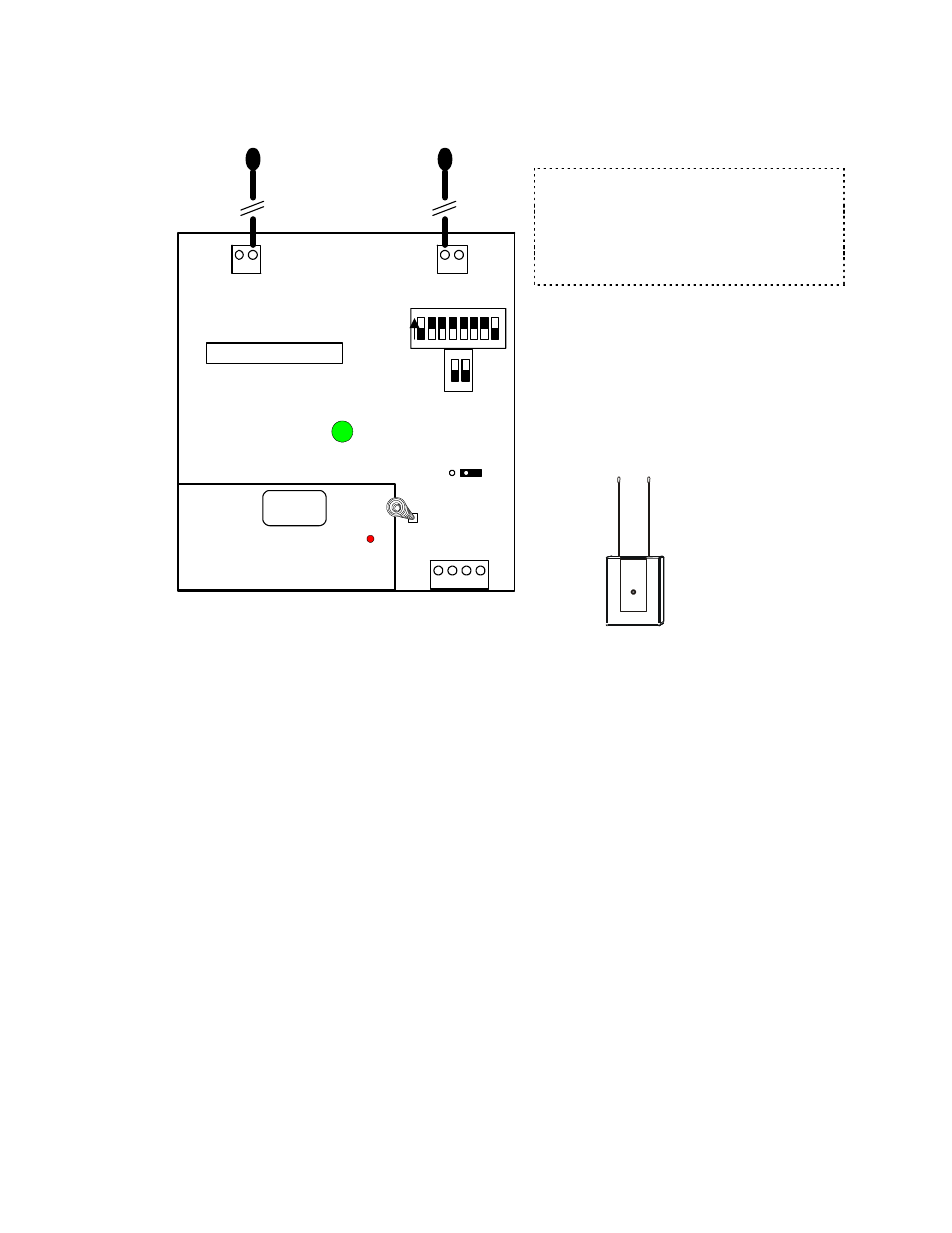
Dip Switch
Settings
must be left
in these
positions.
1 2
1 2
Antennas
Insert in block inner terminals
to align with module cover.
Bus
communications
indicator LED
Tamper
Spring
Power ON LED
and RF reception
indicator.
Module Bus
Interface
Board
J1
Jumper
J1 must
be out.
Monitor RF Module PCB
Current rating = 52mA
5 digit serial number to
program in Module
Programming
XXXXX
•
Referred to as an Application Module.
•
Uses ITI learn mode wireless sensors at 319.5 frequency.
•
Maximum 32 sensors can be programmed per one Version 1 RF module.
•
16 wireless hand held keypads can be programmed per one V1 RF module.
•
Programming is done locally through the LCD keypad. The RF module must be connected to the Module bus to
program.
•
Mount centrally to the wireless sensors.
•
Range approximately 31 meters (100 feet).
•
If more than one V1 RF module is used, separate them 2.5 meters (8.5 feet) apart to prevent interference.
Programming
•
Enter the module’s 5-digit address in Module programming and assign required number of input points for the
number of sensors being used. Do not assign outputs, as there are none. Turn on tamper and all other settings
may remain defaulted. Exit the Module programming and then go back to Module programming and the same
address. This initializes the module.
Hand Held Keypads
•
When back at the same Module programming 5 digit address, press Save.
•
Display
reads
No Keypad
Learn
. The first keypad-programming screen is e.g. M002 A (A = 1
st
keypad).
Keypad programming screens following this one are e.g. M001 B – P for a total of 16 hand held keypads that
can be programmed.
•
Press the right arrow key. Display reads Enroll Keypad.
•
Press the “ f “ (function) key on the hand held keypad.
•
LCD keypad display changes to 00 000.
•
The first 2 zeros represent the area the keypad is assigned to.
•
The next 3 zeros represent the input # the hand held keypad’s panic button (police badge icon) is assigned to.
Reserve a point # in the group of inputs assigned to the RF module for this.
NOTE: If the system’s Feature Set is greater than 5,
Module, Input number Type and Name are
programmed in the Director software program and
sent to the panel. All other wireless sensor
programming described here is done at the system’s
LCD keypad ‘Configs’ screens. Regardless that after
entering Configs, “No Local Edits” displays.
Refer to Installation Instructions P/N 22-0365 for further information.