2 zone wiring – Interlogix Monitor XL Hardware Guide User Manual
Page 12
8
Monitor ISM/xL™ Hardware Guide
22-0375 rev1.1
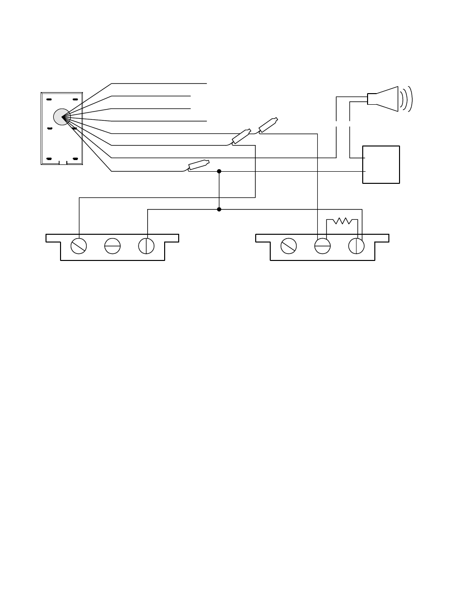
2 Zone Wiring
cont.
ORANGE Protection Point Input # 1
PURPLE Protection Point Input # 2
BLACK Input point
common connection.
Output power source
negative.
RED
GREEN
YELLOW
BLACK
"B"
Co
nn
ect
BLUE Switching to GND Output.
To output driven device.
E.g. electronic siren with
built in driver.
Input # 1 e.g. Main entrance door contact.
Programmed and wired as normally open
with 2.2K end of line resistor.
Input # 2 e.g. Motion detector alarm contact.
Programmed and wired as normally closed.
Protection Input points 1 & 2 and Output Wiring Example
(+)
(--)
2.2 K
NC
NO
CM
NC
NO
CM
Keypad
Base
(back view)
Power
Supply
(+)
(--)
Siren
Separate Data
A,B Cable
S
epar
ate
Po
w
e
r Ca
b
le
M
O
D
U
L
E
B
U
S
Common
Negative
Reference