Modems, Feature expansion board, North american modem – Interlogix Monitor XL Hardware Guide User Manual
Page 53: World wide modem, Interface redcare, Stu interface redcare
22-0375 rev1.1
Monitor ISM/xL™ Hardware Guide
49
Procedure for Cold Booting the Main Control Board and Clearing Memory
1. Remove all power from main control board.
2. Insert the Program Reset Jumpers (CFG0 and CFG1) horizontally. See Program Reset Jumpers on the right side of the main
control module in the “Main Controller” diagram.
3. Apply AC Mains power.
4. The Status and Trouble LEDs will flash on and off together slowly.
5. Remove the 2 jumpers.
6. The same LEDs will momentarily flash rapidly together. (Controller processing)
7. The trouble light will turn off and only the Status LED will flash rapidly.
8. Proceed through the keypad log on procedure explained on page 4 and reset the config. as mentioned on page 4, lower 2
nd
column.
9. The keypad will display regular screens and only the Status LED will flash slowly to indicate a normal condition.
10. The memory has been returned to factory defaults. Reconnect all power.
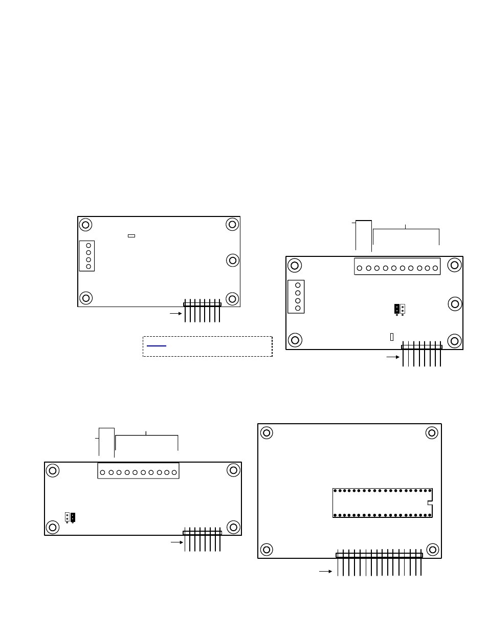
Modems
North American Modem
(Bell 103)
(P/N 650-3630)
Works to Feature set 3
World Wide Modem
(P/N 650-3633)
Works to Feature set 7
3
12
4
Seized Tip
Seized Ring
Tip
Ring
Off Hook
LED
Turns on when
unit dialing out.
Plugs into xL Main Control Board
Modem Expansion Socket
North American Modem
3
12
4
Seized Tip
Seized Ring
Tip
Ring
Off Hook LED
Turns on when
unit dialing out.
Plugs into xL Main Control Board
Modem Expansion Socket
World Wide Modem
7
5
6
8
0V
Line F
a
ilure
9
3
1
2
4
Ou
tput 8
Ou
tput 7
Ou
tput 6
Ou
tput 5
Ou
tput 4
Ou
tput 3
Ou
tput 2
Ou
tput 1
To REDCARE Unit
0
1
1
2
3
2 vertical Jumpers in 1+2 = Output 8 will be 12VDC
high from 0V if main control board CPU fails
2 vertical Jumpers in 2+3 = Output 8 will be 0V low
from 12VDC high if main control board CPU fails
1 Jumper in 1+2 on left side =
Output 8 is a standard output #
8 on this board.
CPU
Failure
with
REDCARE
Interface
From REDCARE Unit
See “ENABLE LINE
FAILURE” next page.
STU
(Subscriber Terminal Unit)
Interface
REDCARE
(P/N 650-3631)
Feature Expansion Board
(P/N 650-3660)
Refer to Installation Instructions P/N 21-3612 for further
information.
7
5
6
8
0V
Li
ne
F
a
ilu
re
Plugs into xL Main Control Board
Modem Expansion Socket
9
3
1
2
4
Outp
u
t 8
Outp
u
t 7
Outp
u
t 6
Outp
u
t 5
Outp
u
t 4
Outp
u
t 3
Outp
u
t 2
Outp
u
t 1
To REDCARE Unit
From
REDCARE Unit
See “ENABLE
LINE FAILURE”
next page.
STU Interface
REDCARE
STU (Subscriber Terminal Unit)
0
1
1
2
3
2 vertical Jumpers in 1+2 = Output 8 will be 12VDC
high from 0V if main control board CPU fails
2 vertical Jumpers in 2+3 = Output 8 will be 0V low
from 12VDC high if main control board CPU fails
1 Jumper in 1+2 on right side = Output 8
is a standard output # 8 on this board.
CPU
Failure
Feature Expansion Board
Feature Expansion Socket
Plugs into xL Main Control Board
Memory Expansion Socket
Refer to Installation Instructions P/N 21-3611 for further information.
Notice: Use minimum 26AWG UL/CSA/or
equivalent approved telephone cable.