Floor selection relay connections – Interlogix Monitor XL Hardware Guide User Manual
Page 40
36
Monitor ISM/xL™ Hardware Guide
22-0375 rev1.1
(+)
1
3
2
1
3
2
1
3
2
1
3
2
1
3
2
1
3
2
13
2
13
2
3
3 1
3
1
1
3
1 2
2
2
2
CO
M
I/
P
3
I/
P
4
I/
P
1
I/
P
2
I/
P
5
I/
P
6
I/
P
8
I/
P
7
CO
M
CO
M
CO
M
1
4
3
2
5
1
2
13
2
RLY1
RLY2
RLY3
RLY4
RLY5
RLY6
RLY7
RLY8
J
5
J
4
J
3
J
2
J
1
J
6
J
7
J
8
CO
M
NC
NO
CO
M
NC
NO
CO
M
NC
NO
CO
M
NC
NO
CO
M
NC
NO
CO
M
NC
NO
COM
NC
NO
COM
NC
NO
(+)
Use all 4
quad cable
wires.
DA
T
A
0
DA
T
A
1
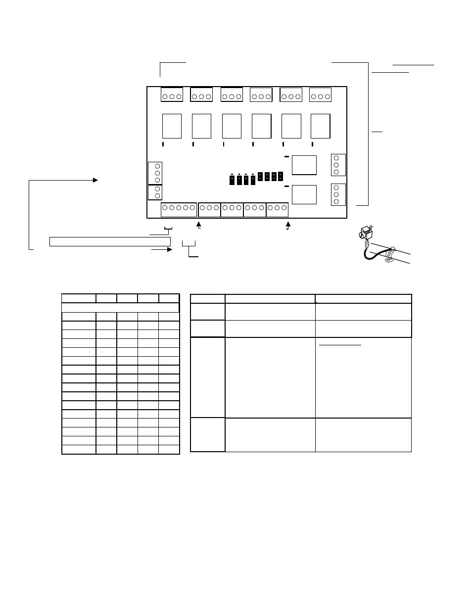
Elevator Relay Board
P/N 650-9035
Floor Selection Relay Connections
Call Button Report Inputs
Terminate cable
shield wires at
cabinet ground lug.
To Elevator Module 1
st
or 2
nd
Elev Data 0
and 1 after going through an Isolator Board.
To Elevator Module 1
st
or 2
nd
Elev Data In,
after going through an Isolator Board
Either of these 2 Data connections can be used to connect
Data In and use the other to run Data out to the next Relay
board.
Relay Board 12VDC
Power Supply In
12VDC Power Out
(Auxiliary)
Relay LED turn on when relay activated.
Earth ground input when a cabinet
ground lug is not available. If quad
cable is used, use all four wires.
Terminate two wires in #1 and two
wires in #2, for convenience.
EARTH
GROUND
GND
Lug
Connect common
earth ground to
cabinet GND lug.
NOTE: The Elevator Relay Board
does not have a module serial
number to program into Module
Programming. The serial # used
is on the Elevator Module.
NOTE: Floor Selection
Relay Wiring: Floor
relays must be wired in
the same relative order
for all elevators (such as
lowest to highest as
accessed from each
specific cab). Remember
basement levels as well.
Tip: When floors are
defined through the
Director software, the
same convention must
be used (e.g., lowest to
highest overall).
The software will display
a Relay Board's address
# and the relay #
assigned to the floor #.
Relay Board's current rating = 340mA.
Board address
jumpers 1 - 4 out =
Relay Board # 1.
(from building elevator control
equipment)
Jumpers J1 - J4
address Elevator Relay Boards
Address
J1
J2
J3
J4
= Jumper IN. (–) = Jumper OUT.
0
–
–
–
–
1
–
–
–
2
–
–
–
3
–
–
4
–
–
–
5
–
–
6
–
–
7
–
8
–
–
–
9
–
–
10
–
–
11
–
12
–
–
13
–
14
–
15
Jumper
IN
OUT
J5
For Wiegand reader
operation.
For Magstripe reader
operation.
J6
Call button report inputs
normally open.
Call button report inputs
normally closed.
J7
Normal operation.
Service Mode
- Call button report inputs
will open or short
(depending on J6)
individually, to trigger
associated relay and test it.
- An “Off Line” condition for
the associated Elevator
Module will indicate, with this
jumper out.
J8
DATA
In or Out
DATA
In
o
r O
u
t
NOTE: The building's
Elevator Company supplies
cable to floor selection relay
connections and call button
report inputs.
(--)
(--)
(Fail Safe
Mode)
All relays energize if
communications lost
between Relay Board and
Elevator Modules.
All relays de-energize if
communications lost
between Relay Board and
Elevator Modules.
Jumpers J5 - J8 select Special Functions
ELEVATOR RELAY BOARD