Ip module v3, Discovery mode program button – Interlogix Monitor XL Hardware Guide User Manual
Page 47
22-0375 rev1.1
Monitor ISM/xL™ Hardware Guide
43
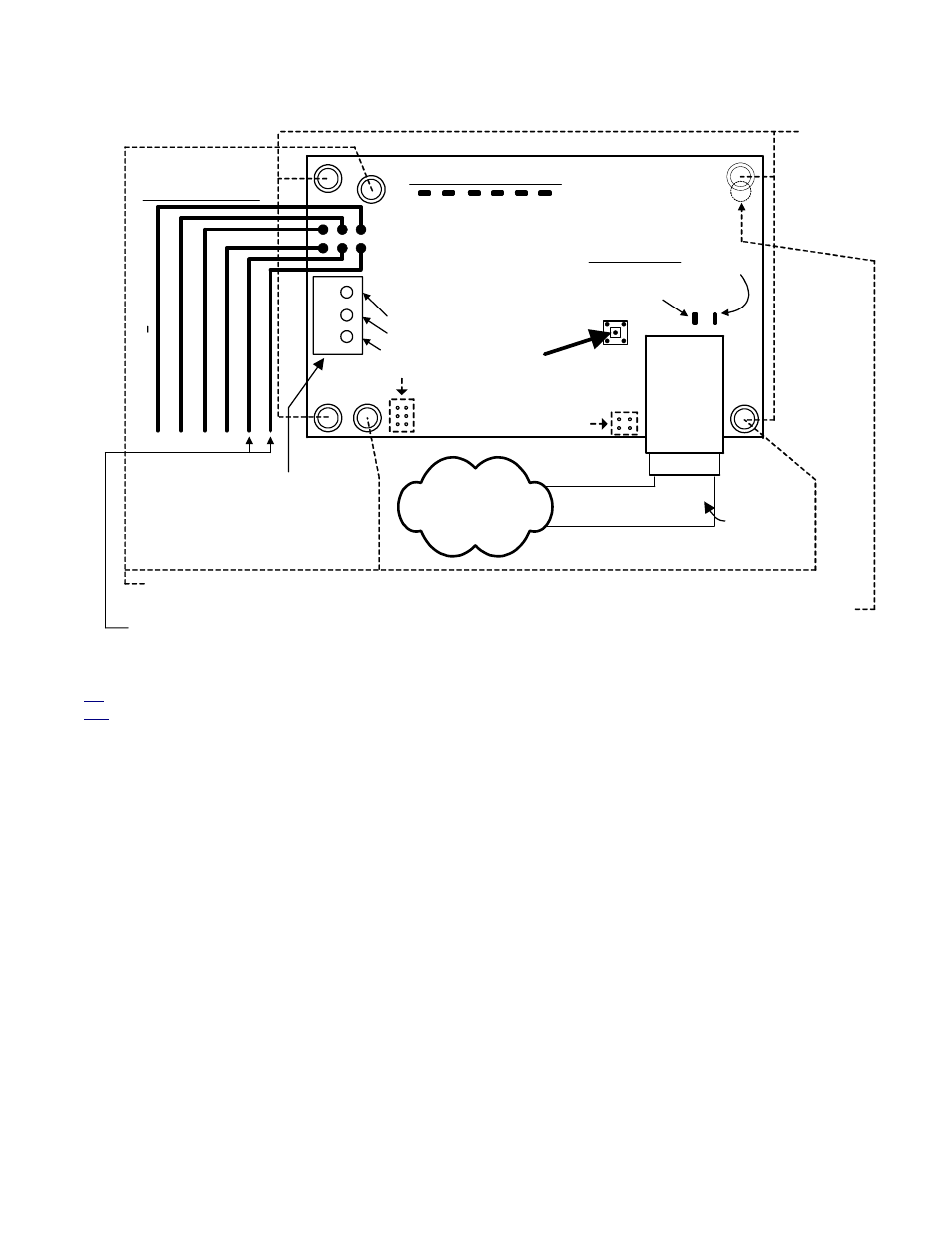
IP Module V3
G
reen
DI
R
R
X
RJ45
Female
Network
Connector
10BaseT
RJ45 Plug
& Cable to
Network
Network LEDS
Green
On = network
connection OK.
Flashing =
network
activity.
1
2
3
Dir RS485 A
Dir RS485 B
Dir Ground
Yel
lo
w
DI
R
TX
Yello
w
SI
P
TX
G
ree
n SIP
R
X
Yel
low
Aux T
X
G
reen
Aux
R
X
Communcation LEDS
This connector can be used
to interconnect additional
panels for Director software
communications.
Not Used
Orange and blue wires can also be
used for “Direct Serial Configuration”.
See Sect. 4.5.2
LAN/WAN
Network
Discovery Mode
Program Button
Wire Connectors
(+)
12VDC
O
range
RS232 R
X
(SIP)
Y
e
llo
w
R
S
485 B (Di
r Sftwr)
Blue
RS232 T
X
(SIP)
G
reen
R
S
48
5 A (
D
ir
ec
tor
Sftwr
)
Re
d
Bl
ack
(
) Neg. G
N
D
These 4
mounting
holes for
new V3 brd
installation
adhesive
stand-offs.
These 3 mounting holes are adaptable to previous version 2 IP
Module adhesive stand-offs.
This is the position where the 4
th
hole for the previous version 2 IP
Module adhesive stand-off would be located but, could not be
accommodated. Cut the existing stand-off pin lower to support this
corner if replacing an existing V2 with a V3 board.
Not Used
V3 IP Module
P2
P3
Yellow
Jumper
Pins
Jumper Pins
Dir: Refers to MONITOR ISM / AFx Director software communications.
SIP: Refers to monitoring station communications (Security IP Receiver reporting).
Refer to the IP Connectivity Guide P/N 22-9059 for programming information.