Wiegand to rs485 interface board, 4 pair travel cable reader wiring, Elevator isolator board – Interlogix Monitor XL Hardware Guide User Manual
Page 43
22-0375 rev1.1
Monitor ISM/xL™ Hardware Guide
39
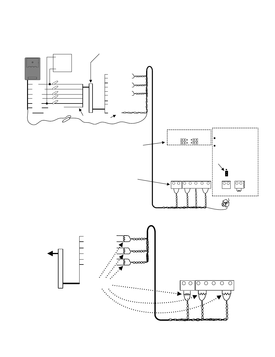
Wiegand to RS485 Interface Board
for longer cable distances (P/N 650-9037)
4 Pair Travel Cable Reader Wiring
12VDC(+)
Reader cable shield. Connect to control unit ground lug.
Elevator
READER
red
orange
white
green
black
brown
LED
Data 0
Data 1
(
-
)Neg
Power
Supply
(+)
(
-
)
"B
" C
on
ne
ct
Wire Connections
Additional 12VDC
power supply
Orange
Blue
Brown
Yellow
White
Purple
Green
Grey
Black
(brown)
Brown Not used for Elevator
Sys. Do not connect.
}
Not
Used
LED
Data 0
Data 1
Data A
Data B
Data A
Data B
Data A
Data B
Twisted 4 Pair Example:
Connect Interface coloured
pairs to twisted pairs with "B"
connectors (P/N 496-1700).
Wh/Brn
Wh/Blu
Reader
(
-
)Neg.
"B" Connect
I
N
T
E
R
F
A
C
E
(orange)
(white)
(green)
(black)
(red)
P/N650-
9037
Blu/Wh
Org/Wh
Wh/Org
Wh/Grn
Grn/Wh
Brn/Wh
The Interface is a small, narrow,
circuit board covered in heat shrink.
It can be located behind the
elevator cab reader, where the
reader cable connections are
made.
Elevator Isolator board Jumper positions
for Normal reader distance: 500 feet
(152 meters) - connect to normal
distance isolator board reader
connections (see figures 8 and 9).
RS485 Jumper positions for
recommended maximum distance of
2000 feet (610 meters) - connect to
these isolator board terminal blocks 9
and 7.
installed on
Elevator
Cab roof.
NOTE: Maximum length of cable allowed for 485 operation may be lower due to cable
capacitance characteristics, card reader technology and manufacturer.
Wh/Br
n
Wh/Bl
u
Bl
u
/W
h
Or
g
/W
h
Wh
/O
rg
Wh
/G
rn
Gr
n
/W
h
Br
n/Wh
4
8
5-
A
G
reen
L
E
D
G
round 0V
3
2
1
4
5
TB9
TB7
Elevator
Isolator
Board
4
8
5-
B G
reen LED
4
8
5
-A Reader
Data1
4
8
5-
B
Reader
Da
ta
1
4
8
5-
A
Reader
Da
ta
0
485-
B Reader
Data 0
2
1
GND Lug
Cable
Shield
Normal
RS485
RS485 Long Distance
Reader Jumper Selection
RS485 Long
Distance
Reader
Connections
G
reen LED
2
1
(
+
) 5 / 12 VDC
TB4
2.2 K
Earth
1 2
TB
1
0
5V
12
V
G
rou
nd
Reader Voltage
Jumper
IMPORTANT NOTE:
Set reader voltage jumper to
5V.
Put a 2.2K ohm resistor
between normal reader pos.
voltage and green LED inputs.
For RS485 operation.
If interference is encountered with 485 communications, terminate all A and B connections at both ends of the reader
cable with 150 ohm resistors, P/N 750-2465 (5%).
Orange
Blue
White
Purple
Green
Grey
LED
Data 0
Data 1
Data A
Data B
Data A
Data B
Data A
Data B
Wh/Blu
I
N
T
E
R
F
A
C
E
P
/N
6
5
0
-903
7
Blu/Wh
Org/Wh
Wh/Org
Wh/Grn
Grn/Wh
Wh
/B
lu
Bl
u
/Wh
Or
g
/W
h
Wh/
O
rg
Wh/
G
rn
Gr
n
/W
h
4
8
5
-A
G
ree
n LED
3
2
1
4
5
TB9
TB7
Elevator Isolator Board
4
85-
B G
ree
n LED
4
8
5
-A
R
ead
er
Da
ta
1
48
5
-B Re
ade
r Da
ta
1
48
5
-A Re
ade
r Da
ta
0
485
-B R
e
a
der D
a
ta
0
2
1
To reader
connections
150 ohm
resistors