Chapter 13 outdoor reset control – AERCO Esteem O&M Manual User Manual
Page 60
54
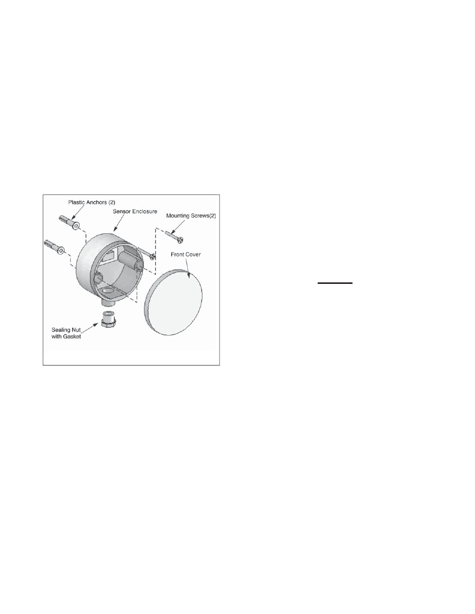
Mounting the Outdoor Sensor
1. Remove the front cover, mounting screws
& anchors from the sensor enclosure.
2. When mounting the enclosure the exterior
wall selected should represent the heat
load of the building. Typically a northern
or northeastern wall will suit most build-
ings. A southern facing wall may suit
buildings that have large glass walls or
windows on the southern face.
3. Ensure the sensor enclosure is shielded
from direct sunlight or the effects of heat
or cold from other sources (exhaust fans,
appliance vents...) to prevent false tem-
perature sensing.
4. Mount the sensor enclosure at an eleva-
tion on the exterior wall to prevent acci-
dental damage or tampering.
5. Avoid mounting the enclosure in areas
subjected to excessive moisture.
6. Once an area on the exterior wall has
been determined, to affix the enclosure
use the enclosure as a template to mark
the location of the mounting screws.
7. Using a 3/16” drill bit, drill 2 pilot holes on
the marked locations.
8. Tap the enclosed plastic anchors into the
pilot holes. Use care not to damage the
anchors.
9. Mount the sensor enclosure using the
screws provided.
Wiring the Sensor
1. Remove the sealing nut and sealing gas-
ket from the sensor enclosure.
2. Route two 18 gauge wires through the
sealing nut and gasket. Connect the wires
to the sensor terminals 1 and 2.
3. Re-insert the sealing gasket and tighten
the sealing nut to the sensor enclosure.
4. Route the sensor wire back to the Esteem
399 Low NOx boiler, ensuring the wires
are not run parallel to telephone or power
cables.
N
OTICE
If the sensor wires are located in an
area with sources of potential electro-
magnetic interference (EMI) the sensor
wires should be shielded or the wires
should be routed in a grounded metal
conduit. If using shielded cable, the
shielding should be connected to the
common ground of the unit.
5. Connect the sensor wires to the outdoor
sensor terminals on the 24V terminal strip
located inside the boiler enclosure (see
boiler wiring diagram, Figure 20 page 34).
Summer / Winter Switch at Boiler
If required the space heating system can be
turned off at the boiler, similar to a manual
summer / winter switch by pressing and holding
the “+” button while in
the “StbY
” mode. The
display will show “
cOFF
”. Pressing and holding
the “+” button turns the space heating system
back on. The display will show “c” followed by
the space heating set point temperature.
Figure 26: Sensor Enclosure and Components
Chapter 13
Outdoor Reset Control
GF-125