AERCO Esteem O&M Manual User Manual
Page 23
17
Additional Limit Control
Additional Limit Control
If a separate LWCO device is required by
certain local jurisdictions or when the boiler is
installed above the system piping, the follow-
ing guidelines must be followed:
• The LWCO device must be designed for
water installations, electrode probe-type
is recommended.
• The LWCO device must be installed in a
tee connection on the boiler supply pip-
ing above the boiler.
• Wiring of the LWCO device to the
Esteem 399 Low NOx is done directly
onto the 24V terminal strip, see Figure
20, page 34 for available terminals for an
external limit (manual or auto reset).
If the installation is to comply with ASME or
Canadian requirements, an additional high
temperature limit may be needed. Consult
local code requirements to determine compli-
ance. The limit should be installed as follows:
• Install the limit in the boiler supply pip-
ing between the boiler and any isolation
valve.
• Maximum set point for the limit is 194ºF.
• For wiring of the limit, see Figure 20,
page 34, using the external limit/manual
reset terminals on the 24V terminal strip.
This will provide a “hard” lockout requir-
ing a manual reset of the control.
Backfl ow Preventer
• Use a backflow preventer valve in the
make-up water supply to the unit as
required by local codes.
Boiler System Piping Applications
All piping applications should use a primary/
secondary piping arrangement as a means to
provide freeze protection of the boiler, which
is an integral function of the boiler control.
Maintain the minimum boiler flow rate, see
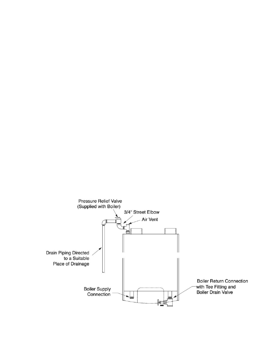
Figure 6: Pressure Relief Valve and Boiler Drain Installation
GF-125