Chapter 8 internal wiring, Warning, General requirements – AERCO Esteem O&M Manual User Manual
Page 39: Control module circulator amp ratings, Wiring tool instructions, Gf-125
33
WARNING
ELECTRICAL SHOCK HAZARD. F
OR
YOUR
SAFETY
,
DISCONNECT
ELECTRICAL
POW
-
ER
SUPPLY
TO
THE
UNIT
BEFORE
SERVICING
OR
MAKING
ANY
ELECTRICAL
CONNECTIONS
TO
AVOID
POSSIBLE
ELECTRIC
SHOCK
HAZARD
.
F
AILURE
TO
DO
SO
CAN
CAUSE
SEVERE
PER
-
SONAL
INJURY
OR
DEATH
.
C
AUTION
Prior to servicing, label all wires before
disconnecting. Wiring errors can cause
improper and dangerous operation.
Verify proper wiring and operation after
servicing.
General Requirements
• Wiring must be NEC Class 1.
• If original wiring as supplied with the unit
must be replaced, use only Type T 90ºC
wire or equivalent as a minimum.
• The Esteem 399 Low NOx must be elec-
trically grounded as required by National
Electrical Code ANSI/NFPA 70 - latest edi-
tion and / or the Canadian Electrical Code
Part 1, CSA C22.1, Electrical Code.
Control Module Circulator AMP
Ratings
- AMP draw of the CH circulator not
to exceed 2 amps.
AMP draw of the DHW circulator not to
exceed 2 amps.
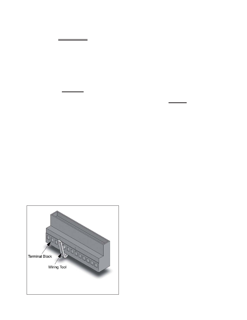
Wiring Tool Instructions
1. Locate the wiring tools on the Esteem 399
Low NOx just below the MCBA control in
a plastic bag and below the extra fuses.
2. Locate the terminal blocks on the Esteem
399 Low NOx below the MCBA control.
N
OTICE
The 120V Terminals are located on the
left set of Terminal Blocks. The 24V Ter-
minals are located on the right set of
terminal blocks.
3. Carefully pull down on the lower half of
the terminal block to remove.
4. Hook the wiring tool into the desired slot
of the terminal block as shown in Figure
19.
5. Push wiring tool in towards the terminal
block and insert wire in slot at bottom of
terminal block.
6. Repeat steps 4 & 5 until all wiring is com-
plete.
7. Re-connect the lower half of the terminal
block to the upper half.
8. Place the wiring tool back into the plastic
bag or leave tool hooked to a slot on the
24V terminal block.
When wiring the Esteem 399 Low NOx allow
additional length of wire for the access panel to
swing open during servicing.
Figure 19: Using the Wiring Tool on the Terminal
Blocks
Chapter 8
Internal Wiring
GF-125