KEYENCE DL-CL1 User Manual
Page 62
3-4 Command Parameter List
3-34
- CC-Link Compatible Network Unit DL-CL1 User’s Manual (SK-1000) -
Comm
u
nic
a
ti
ng
w
it
h th
e
SK-1
000 Se
ri
es
3
*11 By reading the "system parameter current state," the system parameters of the
sensor amplifier can be checked. The system parameters are comprised of the
settings of "judgment output/alarm output" polarity and analog output.
The "system parameter" attribute specifies the system parameters which are set
when the "system parameter set request" is executed by a motion command.
The values to be read or written are specified by translating them to binaries and
using ON or OFF in each bit of the binaries.
Assume the read data is "006":
Translating "6" to a binary number gives "0110".
Thus, the sensor amplifier from which the data was read is set to "NPN
output" and "analog output 1 - 5 V".
*12 This parameter works if "Bank switching method" is set to "button."
*13 These parameters are OFF only if data "0" is written and the wiring is configured
to turn off external input.
*14 A write control error results if data is rewritten to an expansion unit.
*15 To have the sensor amplifier reflect the settings written in data numbers nn92 to
nn95, it is necessary to set data number nn91 to "1" (user setting), or to set the
external input to "user setting" via button operation on the sensor amplifier.
*16 The read value of the two-digit value can be translated to a binary number, so
that the ON/OFF state of each bit can be noted to know the status of judgment
output and alarm output.
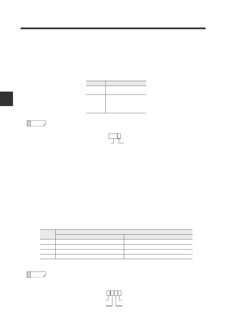
Assume the read data is "05":
Translating "05" to a binary number gives "0101".
N.O. mode
Bit
Setting details
0
0: NPN output
1: PNP output
3, 2, 1
000: Analog output OFF
001: 0 to 5 V
010: -5 to +5 V
011: 1 to 5 V
100: 4 to 20 mA
Reference
Bit 0: NPN output
0 1 1
Bit 3, 2, 1: 1 to 5 V
0
Bit
N.O. mode
N.C. mode
Judgment output
0
1
2
3
0: HI judgment output OFF, 1: HI judgment output ON
0: HI judgment output ON, 1: HI judgment output OFF
0: LO judgment output OFF, 1: LO judgment output ON
0: LO judgment output ON, 1: LO judgment output OFF
0: GO judgment output OFF, 1: GO judgment output ON 0: GO judgment output ON, 1: GO judgment output OFF
0: Alarm output OFF, 1: Alarm output ON
0: Alarm output ON, 1: Alarm output OFF
Reference
0 1 0 1
Bit 3: Alarm output OFF
Bit 2: GO judgment output ON
Bit 0: HI judgment output ON
Bit 1: LO judgment output OFF