Control panel, Standby switch, Allframe – Aviom AllFrame User Manual
Page 53: Ontrol, Anel, Modular i/o frame, All frame
41
f6 f
ronT
P
anel
C
omPonenTs
ALL
FRAME
™
Multi-Modular I/O System
c
oNtrol
P
ANel
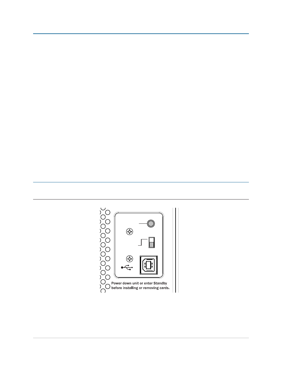
The covered control panel area of the front of the F6 contains the Standby switch, the Control Master switch, and
the USB Type B connector.
To access the switches and connector in the control panel area, remove its cover using a #1 Phillips screwdriver or
5/16-inch hex nut driver.
Standby Switch
The Standby switch is a momentary switch that can be used to force the F6 to enter or exit Standby mode,
allowing I/O cards to be added or removed without having to power-down the entire F6 Modular I/O Frame
unit or disrupt the flow of the A-Net network data to other devices. Standby can also be used when the F6 I/O
resources are not required for a particular application but the F6 needs to remain connected via Cat-5e or fiber
to other Pro64 devices in the network. Standby can also be activated when using Pro64 Network Manager to
monitor the network by using the Standby radio button found in the AllFrame Device Window.
A-Net data always flows through an F6 Modular I/O Frame when it is placed in Standby mode. Always enter
Standby mode or power down the F6 before attempting to remove or reconfigure an F6’s I/O cards.
P
N
ote
:
Do not add or remove I/O cards while the F6 Modular I/O Frame is operating in its full power mode.
Damage to the I/O cards and/or F6 frame itself can occur.
1
2
3
4
C4
m
1
2
3
4
C4
o
1
2
3
4
C4
o
1
2
3
4
C4
o
ALLFRAME
A
B
C
D
E
F
Modular I/O Frame
F6
CONTROL
MASTER
STANDBY
The control panel area with its cover plate removed
The F6 cannot be brought out of Standby mode if the internal temperature is at or above an unacceptable level
caused by the surrounding enclosure’s ambient temperature. The state of Standby mode is preserved across
power cycles.