Installed. (figure 53, “a”), Installing the new power distribution board – Kontron NSN2U IP Network Server User Manual
Page 66
65
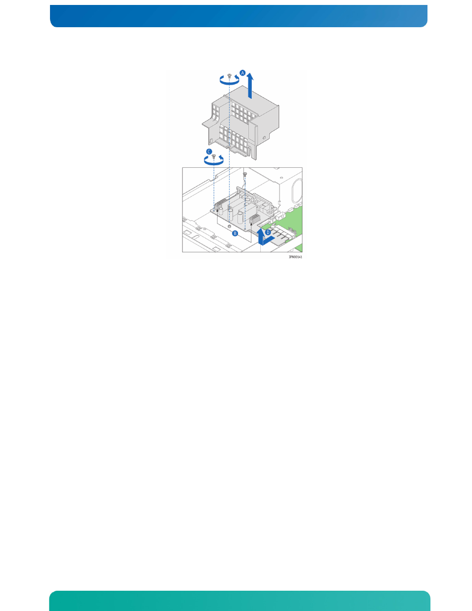
Figure 53. Removing the PDB from the Chassis
Installing the New Power Distribution Board
1. Connect the edge connectors on the new PDB to the T5520UR server board. See Figure
53, “D” for location.
2. Secure the PDB with the two screws reserved from removing the old PDB. See Figure
3. Reconnect the HDD backplane power cable to the header on the PDB See Figure 53, “B”
for location.
4. Replace the black plastic cover and fasten it to the chassis floor. See Figure 53,
“A” for location.
5. Ensure that the optical drive cable and power cable are inside the cover guide
slots.
6. Re-install the SAS/SATA control module or the SAS/SATA hardware RAID module if
either one was installed.
Reconnect the flex cable to the control module and replace the sheet metal cover.
See Section 4.3, “Installing a SAS/SATA Control Module” or Section 4.4, “Installing
a Hardware RAID Module” for help with how to fasten the module, reconnect the flex
cable, and replace the sheet metal cover.
7. Replace the power supply module(s) so they are mated with the PDB.
8. Replace the black plastic riser card assembly/bridge board guide bracket by
loosening the two screws that secure it to the chassis base. See Figure 48 for the
location of this bracket and the screws that attach it.
9. Replace the processor air duct. For instructions, see “Re-Installing the Processor
10. Replace the 60mm PCI fan assembly.
11. Replace the riser card assembly. For instructions, see ”Re-Installing the Riser
Card Assembly” in Section 3.2.
12. If this is the last task you are performing inside the server chassis, replace both
chassis covers, reconnect the power cord(s), and reconnect any external devices.