3 nsn2u server back panel, 4 front panel board – Kontron NSN2U IP Network Server User Manual
Page 15
14
2.3 NSN2U Server Back Panel
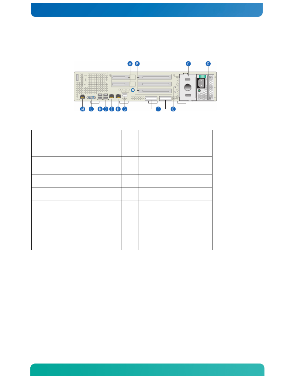
Figure 6 shows the back panel of the NSN2U server.
Figure 6. NSN2U Server Rear View
Item Description
Item Description
A
Two low-profile PCIe add-
in cards (or filler
panels)
H
GbE NIC #2 connector
B
Three full-length PCIe
add-in cards (or filler
panels)
I
GbE NIC #1 connector
C
Power supply 2 (optional,
filler panel shown)
J
USB 2 and 3 (#3 on top)
D
Power supply 1 (AC power
supply shown)
K
USB 0 and 1 (#1 on top)
E
Two ground studs (used for
DC-input system)
L
Video connector
F
Two personality card slots
(for I/O expansion
modules)
M
RJ45 serial port
(Com2/serial B)
G
GCM4 module to enable RMM3
functionality (optional,
filler panel shown)
2.4 Front Panel Board
The front panel (FP) board is located behind the front bezel and in front of the 80 mm
CPU fans. The FP Board provides the following feature set:
•
Three USB ports used for the USB flash drive connector, the combo RJ45 and USB
connector, and a connector reserved for future use
•
Serial RS-232 signals
•
Control circuitry for driving the NIC activity LED, the system status LED, the power
LED and the disk activity LED, all located on the LED/switch board
•
Control circuitry for driving a composite fan fault LED to the LED/switch board
•
On-board LED indicating USB flash drive activity
•
System power state and status indicators -- power, reset, and NMI switches