4 replacing the front panel board, Re-installing the bridge board – Kontron NSN2U IP Network Server User Manual
Page 60
59
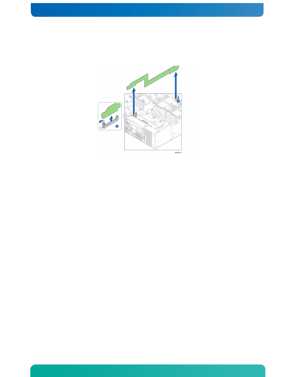
8. Remove the bridge board from the chassis by opening the connector latch clips on
the connectors at both ends of the board and freeing it. (Figure 49, “A”)
The FP board connector latch clip is under the top edge of the chassis front panel.
You cannot see it, but you can feel the latch and unhook it from the board.
Figure 49. Removing the Bridge Board from the Chassis
Re-Installing the Bridge Board
To replace the bridge board back into the chassis:
1. Align the bridge board edge connectors with the headers on the FP board and the
baseboard.
Make sure that the keying slot in the rear bridge board edge connector aligns with
the key in the baseboard card edge connector.
2. Press down to make a firm connection at both ends of the bridge board and refasten
the connector latching clips on each end. (Figure 49)
3. Re-attach the black guide bracket by fastening the two screws to the chassis base.
4. Re-connect the serial port cable. (“B”)
5. Re-connect the SAS/SATA flex circuit cable. (“A”)
6. Re-attach the protective cover on top of the FP board.
7. Re-install the processor air duct.
8. Re-install the riser card assembly.
9. If this is the last task you are performing inside the server chassis, replace both
top chassis covers and reconnect the power cord(s) and any external devices.
5.4 Replacing the Front Panel Board
The front panel board provides the interface to the controls at the front of the
server, the power interconnect for the server board, the USB and serial port B
interface, and it houses the LED/switch board that controls the front panel LEDs. It
also houses the optional low profile USB flash memory.
To replace the FP board, you must first remove the following components:
•
The front chassis cover
•
The black protective cover over the board
•
All cable connections on the FP board