And table 4, 2 installing or replacing hard disk drives – Kontron NSN2U IP Network Server User Manual
Page 40
39
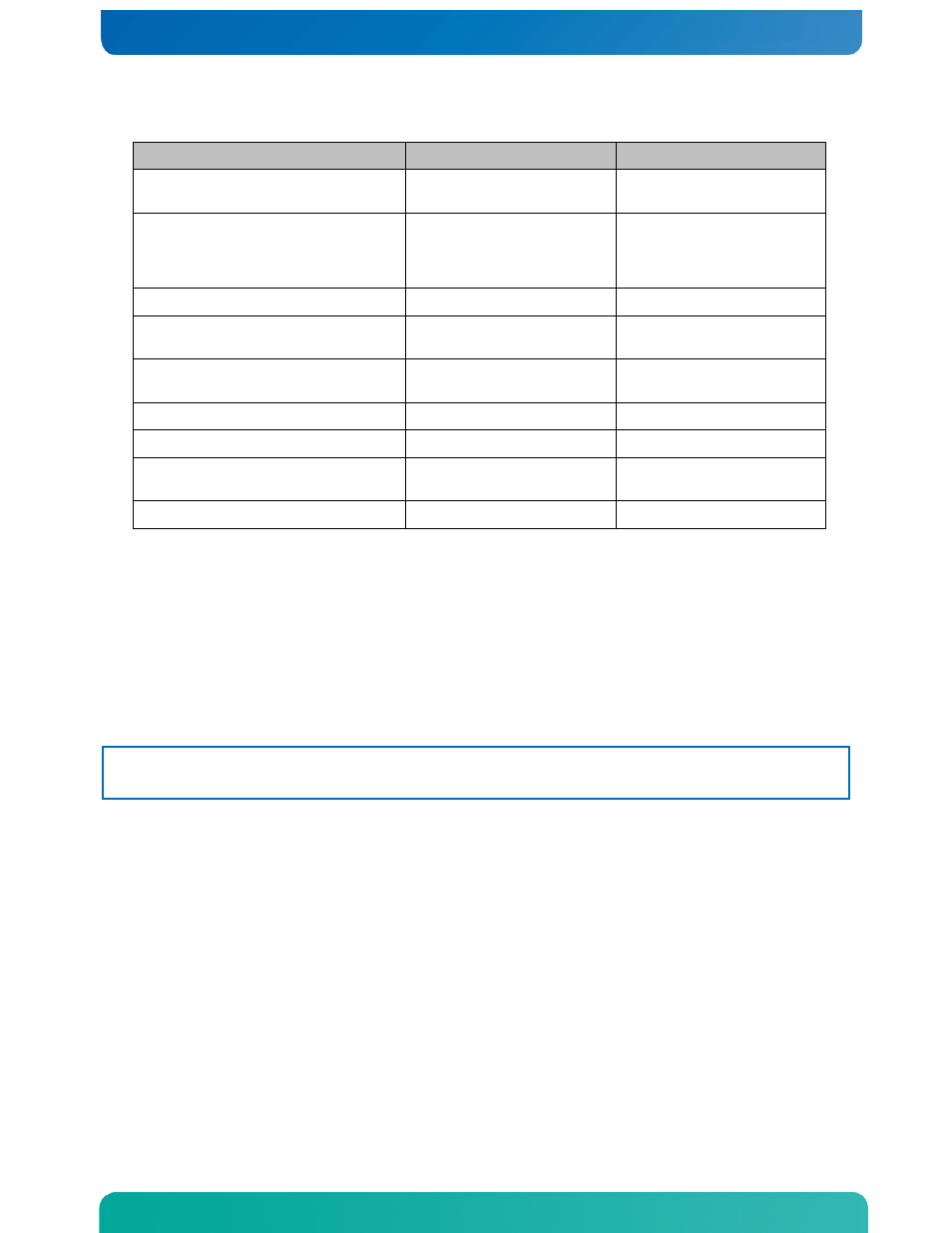
Table 4 System Cables
Cable Number and Name
End 1 Connection
End 2 Connection
1: SAS/SATA Backplane Power
Power distribution
board
SAS/SATA backplane
2: Flex Circuit
SAS/SATA RAID module
or
SAS/SATA Control
module
Bridge board
3: Bridge Board
Baseboard
Front panel board
4: Front Panel Board Power
SAS/SATA backplane
board
Front panel Board
5: LED/Switch Board Power and
Signal
Front panel board
LED/switch board
6: 80mm Fan Power and Signal
Front panel board
Ganged cable to 4 fans
7: 60mm Fan Power and Signal
Front panel board
Ganged cable to 2 fans
8: SATA Optical Drive Power
and Signal
SAS/SATA backplane
board
SATA optical drive
9: Serial Port (COM2)
Bridge board
Baseboard
4.2 Installing or Replacing Hard Disk Drives
Up to eight hot-swappable SAS or SATA hard disk drives can be installed in your NSN2U
server. The drives go into carriers that connect to the SAS/SATA backplane board once
the carriers with drives attached are inserted back into the drive bays. The NSN2U
server ships with four drive carriers in the lower row of drive bays (0 – 3) and
plastic filler panels in the top row of drive bays (4 – 7). If you plan it install
more than four HDDs, you will need to order more drive carriers since only four ship
with the server.
CAUTION: If you install fewer than eight hard disk drives, the unused drive bays must
contain either empty carriers or the filler panels that ship with the server to
maintain proper cooling.
The NSN2U server does not support all SAS/SATA hard disk drives. To see a list of
validated manufacturers and drive models, refer to the THOL. The latest version of
the THOL is located on the
(Search for NSN2U, click on Product Downloads, then Compatibility Matrix).
You must remove the front bezel to add or replace a hard drive in one of the drive
bays. It is not necessary to remove the front chassis cover or to power down the
system. The hard drives are hot-swappable.
Removing an HDD Carrier or Filler Panel from the Chassis
1. Remove the front bezel. For instructions, see “Removing the Front Cover“ in
2. Select the drive bay where you want to install/replace the drive.
Drive bay 0 must be used first, then drive bay 1 and so on.
(Drive bay numbers are printed on the front panel to the right of the bays.)
3. Remove the drive carrier by pressing the green button to open the lever.