3 replacing the bridge board, Removing the bridge board – Kontron NSN2U IP Network Server User Manual
Page 59
58
5.3 Replacing the Bridge Board
The NSN2U server bridge board provides the fan tach and the SAS/SATA signal paths
between the front panel board and the baseboard. Because it spans both the front panel
board and the baseboard, several components must be removed before you can replace the
bridge board:
•
Both top chassis covers
•
The riser card assembly
•
The processor air duct
•
The protective cover on the front panel board
•
The flex circuit cable connection
•
The serial port connection
CAUTION: Before replacing any of the boards on the NSN2U server, you must first take
the server out of service, turn off all peripheral devices connected to the
server, turn off the server by pressing the power button, and unplug the power
cord(s) from the system and wall outlet.
When handling the FP board, observe the normal safety and ESD precautions. See
Appendix A: Safety Information for more information.
For the location of the cables connected to the bridge board, see Figure 7 and Table
Removing the Bridge Board
To remove the bridge board from the chassis:
1. Remove both of the chassis covers. For instructions, see “Removing the Chassis
2. Remove the riser card assembly. For instructions, see “Removing the Riser Card
3. Remove the processor air duct. For instructions, see “Removing the Processor Air
4. Unfasten the black protective cover on top of the FP board.
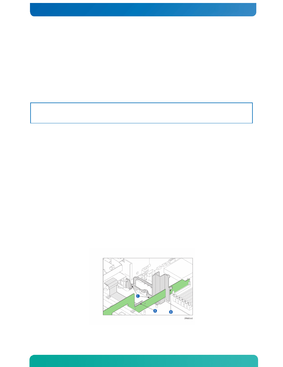
5. Disconnect the SAS/SATA flex circuit cable from the bridge board. (Figure 48, “A”)
6. Disconnect the serial port cable from the bridge board. (“B”)
7. Remove the black plastic riser card assembly/bridge board guide bracket by
loosening the two screws that secure it to the chassis base. (“C”)
Figure 48. Removing Cables and Guide Bracket from the Bridge Board