9 installing an i/o expansion module – Kontron NSN2U IP Network Server User Manual
Page 49
48
4.9 Installing an I/O Expansion Module
The NSN2U server support three different GbE I/O modules and a SAS I/O expansion
module as separately orderable, optional accessories. For information about these
options and how to order them, see the Kontron IP Network Server NSN2U Configuration
Guide
.
This section uses the 10GbE I/O module as the example.
Before installing the I/O expansion module, you must remove the back chassis cover,
the PCI riser card assembly, and the processor air duct.
1. Remove the back chassis cover. For instructions see “Removing the Back Cover” in
2. Remove the riser card assembly (so the processor air duct can be removed). For
instructions see “Removing the Riser Card Assembly” in Section 3.2.
3. Remove the processor air duct. For instructions, see “Removing the Processor Air
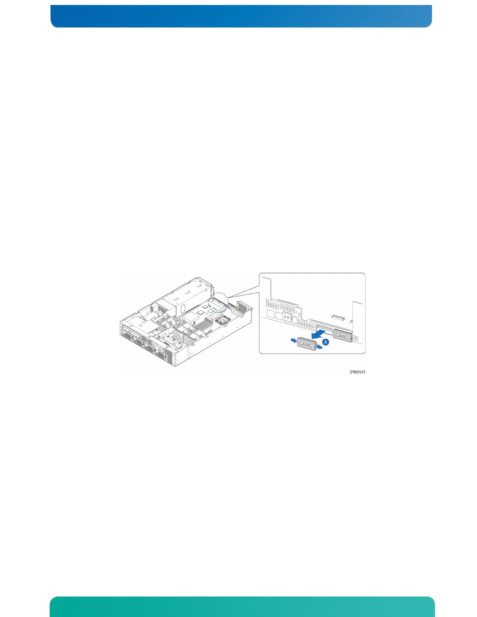
4. For the 10GbE I/O expansion module, both filler panels must be removed.
Squeeze the sides of the I/O expansion module filler panels to remove them from the
rear panel of the chassis. (Figure 38, “A”)
Figure 38. Removing an I/O Expansion Module Filler Panel
5. Locate the three plastic standoffs on the server board or snap them into place if
they are not already installed. (Figure 39, “A”)
6. Attach the double face plate to the I/O module using the two screws. (“B”)
7. Slide the I/O module under the rim of the rear panel and push the module down onto
the three standoffs and the two I/O connectors on the server board. (“C”)
8. Tighten the two screws to secure the I/O module and face plate to the chassis rear
panel. (“B”)
9. If this is the last task you are performing, replace the processor air duct, the
riser card assembly, and the back chassis cover.
Reconnect all the external devices and plug in the power cord(s).
Figure 39. Installing the I/O Expansion Module