Overview, 8 manual resets and lockout conditions, 9 fixed blanking – Banner EZ-SCREEN Low-Profile Safety Light Curtain Systems User Manual
Page 7: 10 inverted display, 11 cascadeable models
P/N 1334
E
5
Banner Engineering Corp.
•
Minneapolis, U.S.A.
www.bannerengineering.com • Tel: 763.544.3164
Overview
P/N 140044 rev.
E
5
Banner Engineering Corp.
•
Minneapolis, U.S.A.
www.bannerengineering.com • Tel: 763.544.3164
EZ-SCREEN LP
Instruction Manual
Overview
1.4.8 Manual Resets and Lockout Conditions
Reset Routine
The EZ-SCREEN LP requires a manual reset to clear a Power-
Up Lockout or Latch condition, and after correcting the cause
of a Lockout condition. This function is designed to provide a
“monitored manual reset” (i.e., open-closed-open action), such
that a shorted or tied-down button cannot cause a reset. When
a key-operated switch is used, this is typically called a key reset.
(Reset switch is sold separately; see Section 2.4 for options.)
To perform a manual reset, close the normally open switch for
at least 1/4 second, but no longer than 2 seconds, and then
re-open the switch. See Sections 3.1.3 and 4.3 for further
information.
A Lockout condition will cause the EZ-SCREEN LP OSSD
outputs to turn OFF. A Lockout condition is indicated by a
flashing Red emitter or receiver Status indicator and an error
number displayed on the Diagnostic Display. Lockout conditions
require a manual reset routine to return the system to RUN
mode after the failure has been corrected. A description of
possible lockouts, their causes, and troubleshooting hints are
listed in Section 5.
Trip Output/Auto Reset
While the use of a reset switch is recommended, it is not
required for receivers configured for Trip Output (automatic
reset). Cycling the supply power (OFF for > 2 seconds, then ON)
will also clear lockouts if their cause has been corrected. If a
reset switch is not used, leave pin 8 (violet wire) not connected
(open) and secure it against shorting to a source of power or
ground.
1.4.9 Fixed Blanking
The fixed blanking feature allows for a stationary object(s)
positioned in the defined area, such as tooling, to be ignored. A
flashing Green Zone indicator denotes the location of a blanked
area. If the object is either moved or removed, the System goes
into Lockout mode, ensuring that an unexpected hole in the
sensing field is not created.
Fixed blanking is easily configured, simply by positioning the
object(s), flipping two DIP switches and resetting the System, as
described in Section 3.4.3.
For cascade models (either when used alone, or as the last
receiver in a cascade), fixed blanking may be configured
remotely; see Section 7.10 for details. This feature is useful
when the light screen is in a difficult-to-access location, or when
the fixed blanked area changes frequently.
1.4.10 Inverted Display
A DIP switch can be used to invert the seven-segment display.
This makes the display “right reading” when an emitter and
receiver are mounted with the QD connector ends up (upside
down). See Section 4.4 for more information.
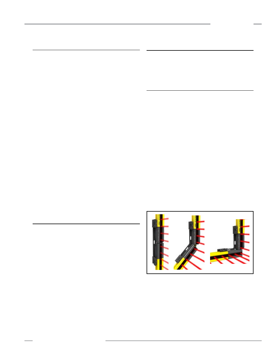
1.4.11 Cascadeable Models
Emitter and receiver models SLPC.. (see Section 7) are capable
of interconnecting up to four emitter/receiver pairs – regardless
of the resolution, the total number of beams, or the size of the
defined area. EZ-SCREEN SLPC.. (cascadeable) models can
also be used individually as stand-alone systems. They also can
be cascaded with EZ-SCREEN SLSC.. models.
Double-ended RD-style 24 AWG cordsets (listed in Section
2.3) are required for connecting sensors in a cascade; see
Section 7.4 for maximum cable lengths. (RD-to-QD cordsets are
available to connect between SLPC.. and SLSC.. models.)
Maximum system response time for a cascade is dependent on
the number of beams in each light screen, and the light screen’s
position in the cascade. It can be calculated in two ways:
• Individually for each light screen in the cascade (safety
distance is calculated for each light screen in the cascade), or
• Based on the worst-case maximum for the entire cascade
(all light screens in the cascade have the same separation
distance).
See Section 7.5 for more information.
Figure 1-4. Fixed-angle brackets allow easy cascading while
maintaining 25 mm resolution