Overview, Cascadeable ez-screen, Warning – Banner EZ-SCREEN Low-Profile Safety Light Curtain Systems User Manual
Page 65: E-stop switch requirements (positive-opening)
P/N 133487
63
Banner Engineering Corp.
•
Minneapolis, U.S.A.
www.bannerengineering.com • Tel: 763.544.3164
Overview
P/N 140044 rev.
E
63
Banner Engineering Corp.
•
Minneapolis, U.S.A.
www.bannerengineering.com • Tel: 763.544.3164
EZ-SCREEN LP
Instruction Manual
Cascadeable EZ-SCREEN
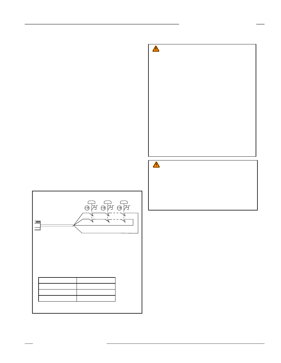
E-Stop Switch Requirements (Positive-Opening)
As shown in Figure 7-8, the E-stop switch must provide two
contact pairs, which are closed when the switch is in the
“armed” position. Once activated, the E-stop switch must open
its contacts and return to the closed-contact position only after
deliberate action (such as twisting, pulling, or unlocking). The
switch should be a “positive-opening type,” as described by
IEC947-5-1. A mechanical force applied to such a button (or
switch) is transmitted directly to the contacts, forcing them
open. This ensures that the switch contacts will open whenever
the switch is activated. ANSI/NFPA 79 specifies the following
additional requirements:
• Emergency Stop push buttons shall be located at each
operator control station and at other operating stations where
emergency shutdown shall be required.
• Stop and Emergency Stop push buttons shall be continuously
operable from all control and operating stations where located.
• Actuators of Emergency Stop devices shall be colored Red.
The background immediately around the device actuator shall
be colored Yellow. The actuator of a push-button-operated
device shall be of the palm or mushroom-head type.
• The Emergency Stop actuator shall be a self-latching type.
NOTE: Some applications may have additional requirements.
The user must comply with all relevant regulations.
Figure 7-8. Hookup of E-stop buttons to the last receiver in the
cascade
WARNING . . .
Reset Routine Required
U.S. and international standards require that a reset routine be
performed after returning the E-stop switch to its closed-contact
position (when arming the E-stop switch). When automatic reset is
used, an alternate means must be established to require a reset
routine, after the E-stop switch is armed. Allowing the machine
to restart as soon as the E-stop switch is armed creates an
unsafe condition which could result in serious injury or death.
WARNING . . .
Multiple E-Stop Switches
• Whenever two or more E-stop switches are connected
to the same EZ-SCREEN LP receiver, the contacts of the
E-stop switches must be connected together in series. This series
combination is then wired to the respective EZ-SCREEN LP
receiver input.
Never connect the contacts of multiple E-stop switches in
parallel to the EZ-SCREEN LP inputs; this defeats the switch
contact monitoring ability of the EZ-SCREEN LP light curtain,
and creates an unsafe condition which could result in
serious bodily injury or death.
• Also, when two or more E-stop switches are used, each
switch must be individually actuated (engaged), then
re-armed and the EZ-SCREEN LP light curtain reset (if using
latch mode). This allows the monitoring circuits to check each
switch and its wiring to detect faults. Failure to test each switch
individually in this manner could result in undetected faults
and create an unsafe condition which could result in serious
bodily injury or death.
Combination DELPEF-8..D / QDE2R4-8..5D Cordset Pinout**
Pin #1 ― Brown (Ch 1a)
Pin #5 ― Blue (Ch 2b)
Pin #2 ― n.c.
Pin #6 ― n.c.
Pin #3 ― n.c.
Pin #7 ― n.c.
Pin #4 ― Black (Ch 1b)
Pin #8 ― White (Ch 2a)
** Standard M12 / Euro-style cordsets (8-pin male QD) can also be
used, although pin number / wire color must be verified.
RDLP6G-4..D Cordset Pinout*
Brown ― Ch 1a
White ― Ch 2a
Blue ― Ch 2b
Black ― Ch 1b
* Other cordset options may also be used; see below for more information.
Wh
E-Stop 1 E-Stop 2 E-Stop N
Bk
Bn
Bu
RDLP6G-4..D