Overview, Installation and alignment – Banner EZ-SCREEN Low-Profile Safety Light Curtain Systems User Manual
Page 34
32
P/N 133487
Banner Engineering Corp.
•
Minneapolis, U.S.A.
www.bannerengineering.com • Tel: 763.544.3164
Overview
32
P/N 140044 rev.
E
Banner Engineering Corp.
•
Minneapolis, U.S.A.
www.bannerengineering.com • Tel: 763.544.3164
EZ-SCREEN LP
Instruction Manual
Installation and Alignment
4. Optical Alignment
CAUTION: Ensure that no individuals are exposed to any
hazard if the OSSD outputs turn ON when the
emitter and receiver become aligned.
Verify sensor mounting per Section 3.2.
Verify Optimal Alignment (Rotate with power ON)
a. Ensure the emitter and receiver are pointed squarely
at each other. A straight edge (e.g., a level) can determine
the direction the sensor is facing (see Figure 3-14). The
sensor face must be perpendicular to the optical axis.
NOTE: At power-up, the EZ-SCREEN LP tests all indicators
(they flash), then displays the Scan Code.
b. If Channel #1 beam is not aligned, the receiver Status
and Zone 1 indicators are Red, the Reset indicator is
Yellow, and the 7-segment display sequentially indicates
“CH1”. Zone indicators 2-8 will be OFF.
c. If the Green Status and Yellow Reset indicators are ON,
go to step “d”. If not, rotate each sensor (one at a time)
left and right until the Status indicator comes ON Green.
(As the sensor rotates out of alignment, the Status indicator
will turn ON Red.) As more beams are made, the Zone
indicators will turn from Red to Green and the number of
blocked beams displayed will decrease.
NOTE: If the emitter Test input is open, the 7-segment
Display will indicate the total number of beams in
the system (minus one) and all Zone indicators will
be Red (except for 14-beam systems, where Zone 1
indicator will be Green).
d. To optimize alignment and maximize excess gain,
slightly loosen the sensor mounting screws and rotate
one sensor left and right, noting the positions in each arc
where the Status indicators turn Red (Blocked condition);
repeat with the other sensor (see Figure 3-14). Center
each sensor between those two positions and tighten the
mounting screws, making sure to maintain the positioning
as the screws are tightened.
For situations where alignment is difficult, a LAT-1-LP
Laser Alignment Tool can be used to assist or confirm
alignment by providing a visible red dot along the sensor’s
optical axis (see Figure 3-16).
e. If, at any time, a Status indicator begins to flash Red, that
sensor has entered a Lockout condition. See Section 5.1.1
for further information.
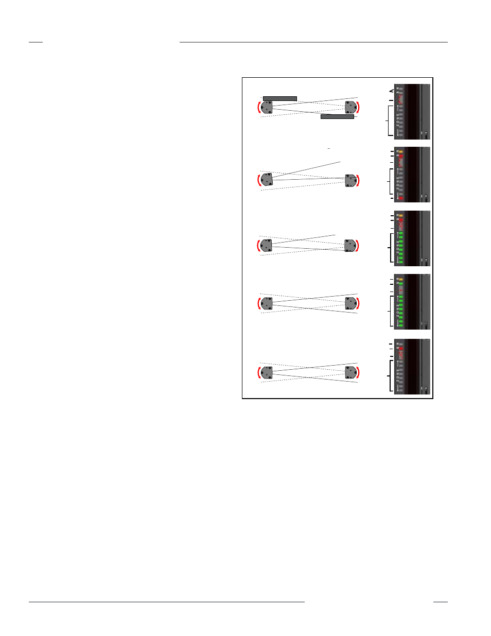
Figure 3-14. Optimum optical alignment
All
OFF
C1 or C2
OFF
OFF
CH1
Yellow
Red
ON Red
or
Green
# Beams Blocked
Yellow
Green
ON
Green
OFF
Flashing Red
All
OFF
Flashing Error Code
ON Red
Dash
e.
a.
b.
c.
d.
Straight Edge
Straight Edge
Yellow
Red