Overview, Installation and alignment, 6 adjacent reflective surfaces – Banner EZ-SCREEN Low-Profile Safety Light Curtain Systems User Manual
Page 27: Warning
P/N 133487
25
Banner Engineering Corp.
•
Minneapolis, U.S.A.
www.bannerengineering.com • Tel: 763.544.3164
Overview
P/N 140044 rev.
E
25
Banner Engineering Corp.
•
Minneapolis, U.S.A.
www.bannerengineering.com • Tel: 763.544.3164
EZ-SCREEN LP
Instruction Manual
Installation and Alignment
d
d
d
Operating Range
(R)
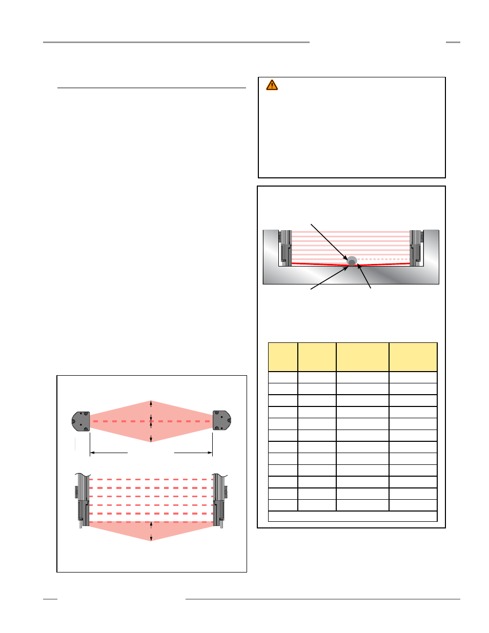
Emitter
Receiver
Do not position reflective surfaces
within the shaded area
top view
side view
Figure 3-6. Adjacent reflective surfaces
3.1.6 Adjacent Reflective Surfaces
A reflective surface adjacent to the defined area may deflect
one or more beams around an object in the defined area. In
the worst case, an “optical short circuit” may occur, allowing an
object to pass undetected through the defined area (see Figure
3-6).
This reflective surface may result from shiny surfaces or glossy
paint on the machine, the workpiece, the work surface, the floor
or the walls. Discover beams deflected by reflective surfaces by
performing the trip test portion of the final alignment procedure
and the periodic checkout procedures (Section 3.4.4).
To eliminate problem reflections:
• If possible, relocate the sensors to move the beams away
from the reflective surface(s), being careful to maintain
adequate safety (minimum) distance (see Figure 3-6).
• Otherwise, paint, mask or roughen the shiny surface to
reduce its reflectivity.
• Where these are not possible (as with a shiny workpiece or
machine frame), determine the worst-case resolution resulting
from the optical short circuit and use the corresponding depth
penetration factor (Dpf) in the safety (minimum) distance formula
(see Figure 3-7 and Section 3.1.1); or mount the sensors in
such a way that the receiver’s field of view and/or the emitter’s
spread of light are restricted from the reflective surface.
• Repeat the trip test to verify that the changes eliminated
the problem. If the workpiece is especially reflective and
comes close to the defined area, perform the trip test with the
workpiece in place.
Use the table below to calculate Dpf or Factor “C” when a shiny surface
causes an optical short circuit.
Test
Piece
Model
Resolution
Depth Penetration
Factor for U.S.
Applications
Factor “C”
for European
Applications
STP-13
14 mm
24 mm (1")
0 mm
STP-2
19 mm
41 mm (1.6")
40 mm (1.6")
STP-16
25 mm
61 mm (2.5")
88 mm (3.5")
STP-14
30 mm
78 mm (3")
128 mm (5")
STP-4
32 mm
85 mm (3.3")
144 mm (5.7")
STP-17
34 mm
92 mm (3.6")
160 mm (6.3")
STP-1
38 mm
106 mm (4.2")
192 mm (7.6")
STP-3
45 mm
129 mm (5")
850 mm (33.5")
STP-8
51 mm
150 mm (5.9")
850 mm (33.5")
STP-5
58 mm
173 mm (6.8")
850 mm (33.5")
STP-15
60 mm
180 mm (7")
850 mm (33.5")
STP-12
62 mm
187 mm (7.4")
850 mm (33.5")
See Section 3.1.1 for Safety (Separation) Distance calculation information
Figure 3-7. Increasing resolution value to mitigate an optical short
circuit
Optical Short
Circuit
Increasing the size of the test piece to
block additional beams will cause a blocked
condition. The size of the test piece required
to do this will determine the actual resolution.
Reflective Surface
At the midpoint of the defined area, a test piece (represented by the
darker circle) with the specified system resolution does not cause
a blocked condition, due to an optical short circuit. Zone indicator
LEDs are ON Green and the OSSDs are ON.
WARNING . . .
Avoid Installation Near
Reflective Surfaces
Avoid locating the defined area near a reflective surface; it could
reflect sensing beam(s) around an object or person within the
defined area, and prevent its detection by the EZ-SCREEN LP
System. Perform the trip test, as described in Section 3.4.4, to
detect such reflection(s) and the resultant optical short circuit.
Failure to prevent reflection problems will result in incomplete
guarding and could result in serious bodily injury or death.
Emitter
Receiver
Do not position reflective surfaces within the shaded area
Operating Range
(R)
At installed operating range (R): d = 0.0437 × R (m or ft)
Operating range 0.1 to 3 m (4" to 10'): d = 0.13 m (5")
Operating range > 3 m ( > 10'):
d = 0.0437 × R (m or ft)