Overview, Installation and alignment – Banner EZ-SCREEN Low-Profile Safety Light Curtain Systems User Manual
Page 30
28
P/N 133487
Banner Engineering Corp.
•
Minneapolis, U.S.A.
www.bannerengineering.com • Tel: 763.544.3164
Overview
28
P/N 140044 rev.
E
Banner Engineering Corp.
•
Minneapolis, U.S.A.
www.bannerengineering.com • Tel: 763.544.3164
EZ-SCREEN LP
Instruction Manual
Installation and Alignment
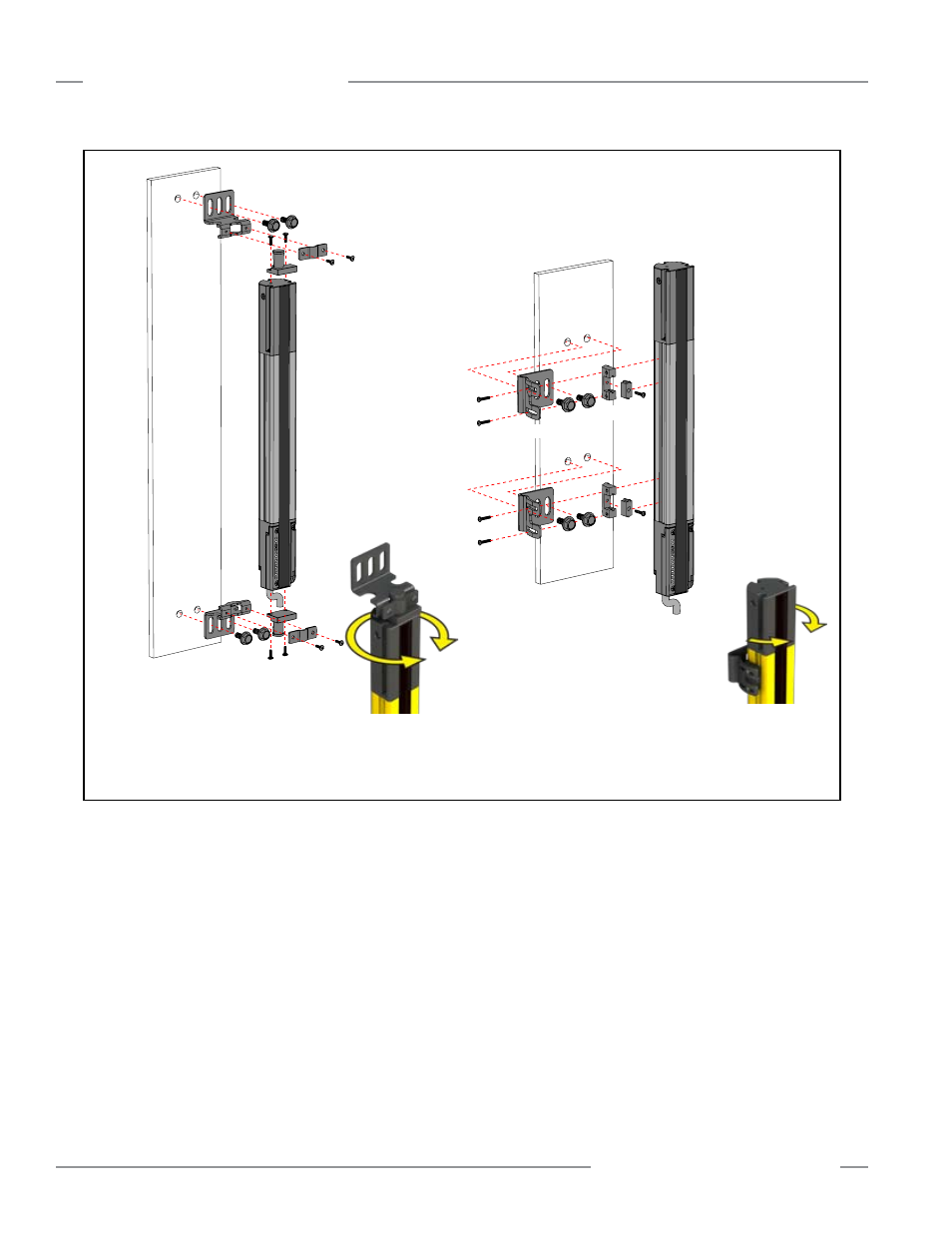
Fig ure 3-10. Emit ter and re ceiv er mounting hardware (see Appendix A for more information)
Mounting the Side-Mount Brackets
1. From a common point of reference (ensuring the minimum
safety distance calculated in Section 3.1.1), measure to
locate the emitter and receiver in the same plane, with their
midpoints directly opposite each other. Important: The
connector ends of both sensors must point in the same
direction (see Figure 3-5 and warning, Section 3.1.4).
Mount the emitter and receiver mounting brackets to the
desired surface, using the supplied M5 bolts and nuts or
user-supplied hardware; see Figure 3-10.
2. Attach the 2-piece clamp to the sensor housing side
channels (either side of the housing) at the appropriate
locations, using the supplied M3x6 screws.
3. Attach the clamp to the bracket, using the supplied M5
screws.
4. Position the emitter and receiver windows directly facing each
other. Measure from a reference plane (e.g., a level building
floor) to the same point(s) on the emitter and receiver to
verify their mechanical alignment. Use a carpenter’s level, a
plumb bob, or the optional LAT-1 Laser Alignment Tool (see
Section 2.5) or check the diagonal distances between the
sensors, to achieve mechanical alignment; see Figure 3-11.
Final alignment procedures are explained in Section 3.4.
5. Tighten all fasteners.
NOTES:
• EZ-SCREEN LP sensor brackets are designed to mount directly to MSA
Series stands (Section 2.3), using the hardware supplied with the stands.
• See Figure 2-1 for mounting bracket dimensions.
* Emitters and Receivers 830 mm and longer also include an additional side-mount
bracket for center support; sensors 1390 mm and longer include 2 (total 4)
Sensors are designed to be mounted with up to 690 mm unsupported
distance between brackets (see Section 3.2.1).
Side-Mount Brackets
(2 or more*
supplied with each emitter and receiver
)
Sensors may be mounted with all side-mount brackets, or a
combination of side-mount and end-mount brackets.
End-Mount Brackets
(2 supplied with each emitter and receiver)
Bracket
Clamp
360°
Rotation
−30°
rotation
+10°
rotation