Overview, Cascadeable ez-screen, 7 configuration for cascaded operation – Banner EZ-SCREEN Low-Profile Safety Light Curtain Systems User Manual
Page 64: 8 emergency stop buttons and devices, Warning
62
P/N 133487
Banner Engineering Corp.
•
Minneapolis, U.S.A.
www.bannerengineering.com • Tel: 763.544.3164
Overview
62
P/N 140044 rev.
E
Banner Engineering Corp.
•
Minneapolis, U.S.A.
www.bannerengineering.com • Tel: 763.544.3164
EZ-SCREEN LP
Instruction Manual
Cascadeable EZ-SCREEN
7.7 Configuration for Cascaded Operation
Each cascaded system must be configured, before it can be run
in a production environment.
Before configuration, install all emitters and receivers per
Sections 3 and 7. The last SLPCR-.. receiver must be
terminated either with a terminator plug, or with an EZA-
RBK-1 remote key switch box, or by connecting two closed
mechanical contacts (see Sections 7.8 and 7.9).
Perform the following procedure on the first receiver only in
the cascade (closest to the machine interface). Other than scan
code, set all other receivers in the cascade to the factory default
positions.
1. From either normal operation or a power OFF condition, set
the first and fourth DIP switches (T/L and Red Res) both
to the left (Trip operation and Reduced Resolution enabled
positions). See Figure 7-7.
2. Set the second and third DIP switches (Red Res and T/L)
both to the right (Reduced Resolution OFF and Latch
operation positions).
3. The receiver should be in a lockout condition or power OFF.
4. If power is OFF: Apply power
Lockout condition: Perform a valid reset sequence (close
the reset switch for 0.25 to 2 seconds, then reopen).
5. Coming out of lockout or during startup, the DIP switch
configuration will be recognized as Cascaded Teach Mode,
indicated by the following:
• First receiver display sequentially shows
No E-stop connected: “4C,” “3C,” or “2C”
E-stop w/closed contacts: “4CE,” “3CE,” or “2CE”
E-stop w/open contacts: “4CO,” “3CO” or “2CO”
• Last cascaded receiver display sequentially shows
Terminator connected: “1C”
E-stop w/closed contacts: “1CE”
E-stop w/open contacts: “1CO”
• Other receivers sequentially display “1C”
• All receiver Zone indicators OFF
• All receiver Yellow Reset indicators OFF
• All receiver Status indicators solid red
6. To enable and exit Cascade Teach Mode, reconfigure DIP
switches for normal operation.
7. Perform a valid reset sequence (see Step 4), or cycle power.
7.8 Emergency Stop Buttons and Devices
Cascadeable EZ-SCREEN LP receivers may be connected to one
or more E-stop buttons. The button(s) must connect to the end of
the last receiver in the cascade, in place of the terminator plug.
The connected E-stop button(s) will activate/deactivate the
OSSD outputs in all receivers in the cascade.
The number of E-stop buttons allowed in a series connection is
limited by the total resistance per channel. The total resistance
is the sum of all contact resistance values in the channel, plus
the total wire resistance in the channel. The maximum total
resistance per channel is 100 Ohms.
NOTE: The simultaneity between the two E-stop contacts, on
opening and closing, is 3 seconds. If simultaneity is not
met on either opening or closing, the last receiver’s display
will flash “|-|”. If simultaneity is not met on opening, the
closed contact can be opened later (after more than 3
seconds), then both contacts must be closed again.
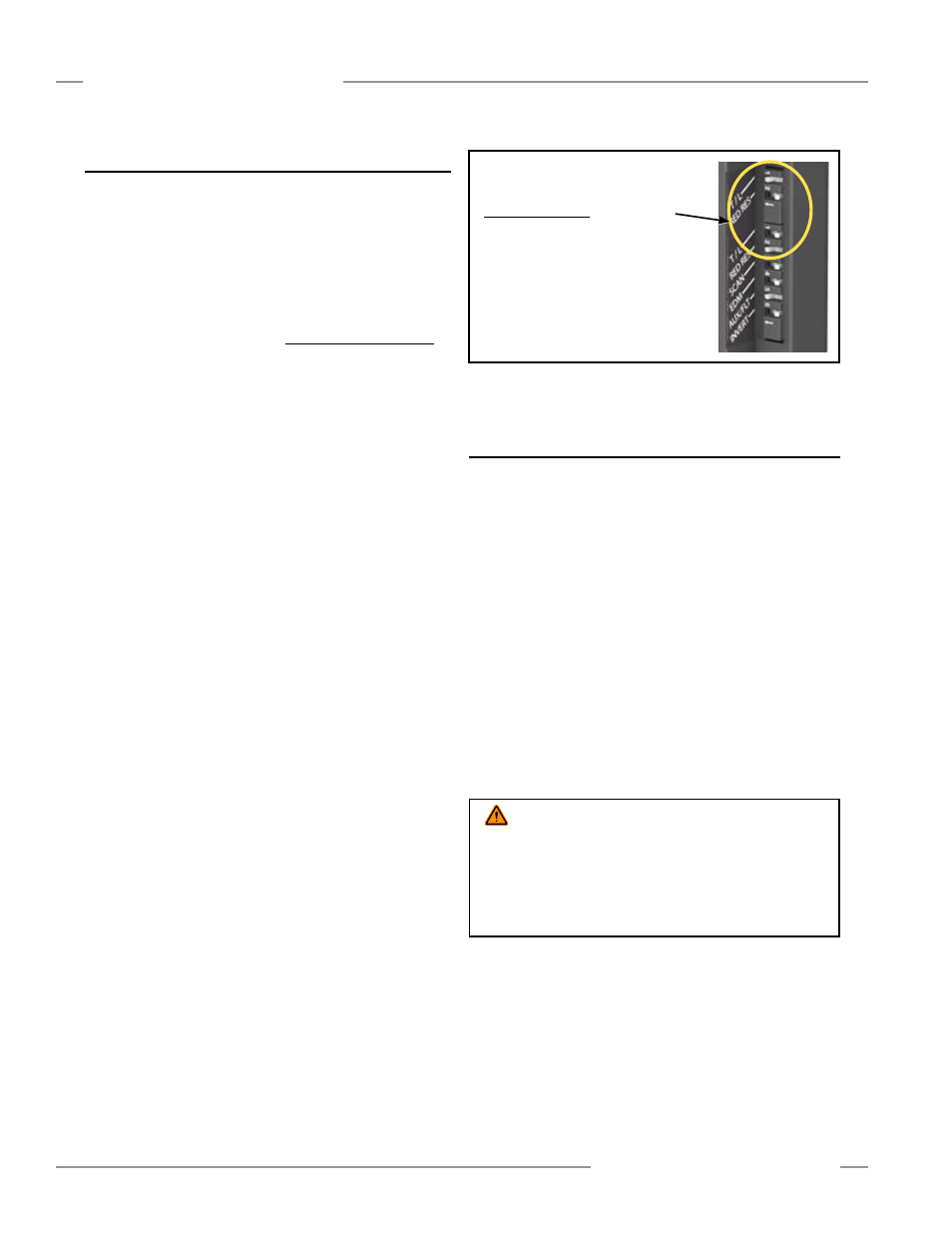
Figure 7-7. DIP switch configuration to enable cascade installation
1. Install cascade system per Sections 3 and 7 of
this manual.
With Power ON:
2. On the first receiver only, set the T/L and
Red Res switches as shown (do not change
SCAN or EDM switch positions).
3. Press the Reset button or cycle power.
4. Reconfigure DIP switches for normal operation.
5. Press the Reset button or cycle power.
NO TE: If the EDM wiring does not match the switch
position, an EDM error occurs and cascade
configuration will not be allowed.
WARNING . . .
Emergency Stop Functions
If Cascade Input is used for an Emergency Stop function, do not
mute or bypass the safety outputs (OSSDs) of the EZ-SCREEN LP.
ANSI/NFPA79 and IEC 60204-1 require that the Emergency Stop
function remain active at all times. Muting or bypassing the safety
outputs will render the Emergency Stop function ineffective.