Overview, Cascadeable ez-screen, 9 positive-opening safety interlock switches – Banner EZ-SCREEN Low-Profile Safety Light Curtain Systems User Manual
Page 66: Warning
64
P/N 133487
Banner Engineering Corp.
•
Minneapolis, U.S.A.
www.bannerengineering.com • Tel: 763.544.3164
Overview
64
P/N 140044 rev.
E
Banner Engineering Corp.
•
Minneapolis, U.S.A.
www.bannerengineering.com • Tel: 763.544.3164
EZ-SCREEN LP
Instruction Manual
Cascadeable EZ-SCREEN
7.9 Positive-Opening Safety Interlock Switches
The Cascade input may be used to monitor interlock safety
gates or guards. Requirements vary widely for the level of
control reliability or safety category (per ISO 13849-1) in the
application of interlocked guards. While Banner Engineering
recommends the highest level of safety in any application, it
is the responsibility of the user to safely install, operate, and
maintain each safety system and comply with all relevant laws
and regulations. Of the following applications, Figure 7-9 meets
or exceeds the requirements for OSHA/ANSI control reliability
and Safety Category 4, per ISO 13849-1.
The safety switches and actuators used with the Cascade must
be designed and installed so that they cannot be easily defeated.
They must be mounted securely, so that their physical position
can not shift, using reliable fasteners that require a tool to
remove. Mounting slots in the housings are for initial adjustment
only; final mounting holes must be used for permanent location.
Positive-Opening Interlocking Safety Switches
Two individually mounted safety interlock switches are
recommended for each guard to meet Category 4, per ISO
13849-1, and must satisfy several requirements. Each switch
must provide at minimum, one normally closed (N.C.) electrically
isolated contact to interface with the Cascade input (see
Figure 7-9).
The contacts must be of “positive-opening” design, with one or
more normally closed contacts rated for safety. Positive-opening
operation causes the switch to be forced open, without the use of
springs, when the switch actuator is disengaged or moved from
its home position (see the Banner Safety Catalog for examples).
In addition, the switches must be mounted in a “positive mode”
to move/disengage the actuator from its home position and open
the normally closed contact when the guard opens.
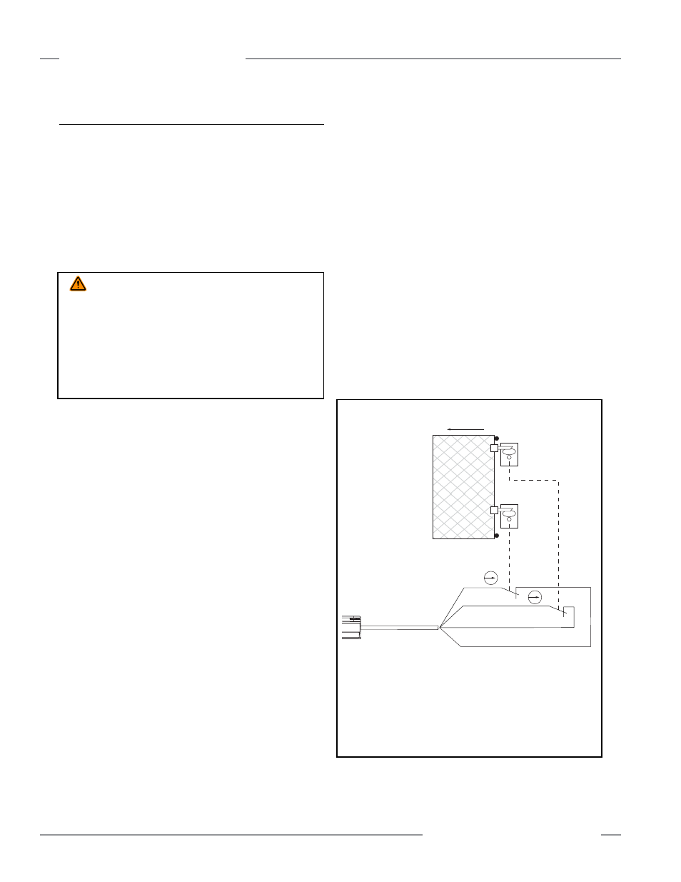
Figure 7-9. Monitoring two positive-opening safety switches
Interlock Guarding Requirements
The following general requirements and considerations apply to
the installation of interlocked gates and guards for the purpose
of safeguarding. In addition, the user must refer to the relevant
regulations to be sure to comply with all necessary requirements.
Hazards guarded by the interlocked guard must be prevented
from operating until the guard is closed; a Stop command must
be issued to the guarded machine if the guard opens while the
hazard is present. Closing the guard must not, by itself, initiate
hazardous motion; a separate procedure must be required to
initiate the motion. The safety switches must not be used as a
mechanical or end-of-travel stop.
The guard must be located an adequate distance from the
danger zone (so the hazard has time to stop before the guard
is opened sufficiently to provide access to the hazard), and it
must open either laterally or away from the hazard, not into the
safeguarded area. Depending on the application, an interlocked
gate or door should not be able to close by itself and activate
the interlocking circuitry (ANSI/RIA R15.06). In addition, the
installation must prevent personnel from reaching over, under,
around, or through the guard to the hazard. Any openings in the
guard must not allow access to the hazard (see ANSI B11.19 or
the appropriate standard). The guard must be strong enough and
designed to protect personnel and contain hazards within the
guarded area, which may be ejected, dropped, or emitted by the
machine.
WARNING . . .
Unguarded Moving Parts
It must not be possible for personnel to reach any hazard point
through an opened guard (or any opening) before hazardous
machine motion has completely stopped.
Please reference OSHA CFR1910.217, ANSI B11 standards, or
other appropriate standards for information on determining safety
distances and safe opening sizes for your application (see Inside
back cover).
Wh
Open
Bk
Bn
Bu
NOTE: This application is considered
to meet or exceed requirements
for OSHA/ANSI control reliability
and Category 4 per ISO 13849-1.
RDLP6G-4..D
RDLP6G-4..D Cordset Pinout*
Brown ― Ch 1a
White ― Ch 2a
Blue ― Ch 2b
Black ― Ch 1b
* Other cordset options may also be used; see Figure 7-8 for more
information.