Overview, Cascadeable ez-screen, 6 cascaded sensor configuration settings – Banner EZ-SCREEN Low-Profile Safety Light Curtain Systems User Manual
Page 63: 1 fixed blanking, Warning
P/N 13348
61
Banner Engineering Corp.
•
Minneapolis, U.S.A.
www.bannerengineering.com • Tel: 763.544.3164
Overview
P/N 140044 rev.
E
61
Banner Engineering Corp.
•
Minneapolis, U.S.A.
www.bannerengineering.com • Tel: 763.544.3164
EZ-SCREEN LP
Instruction Manual
Cascadeable EZ-SCREEN
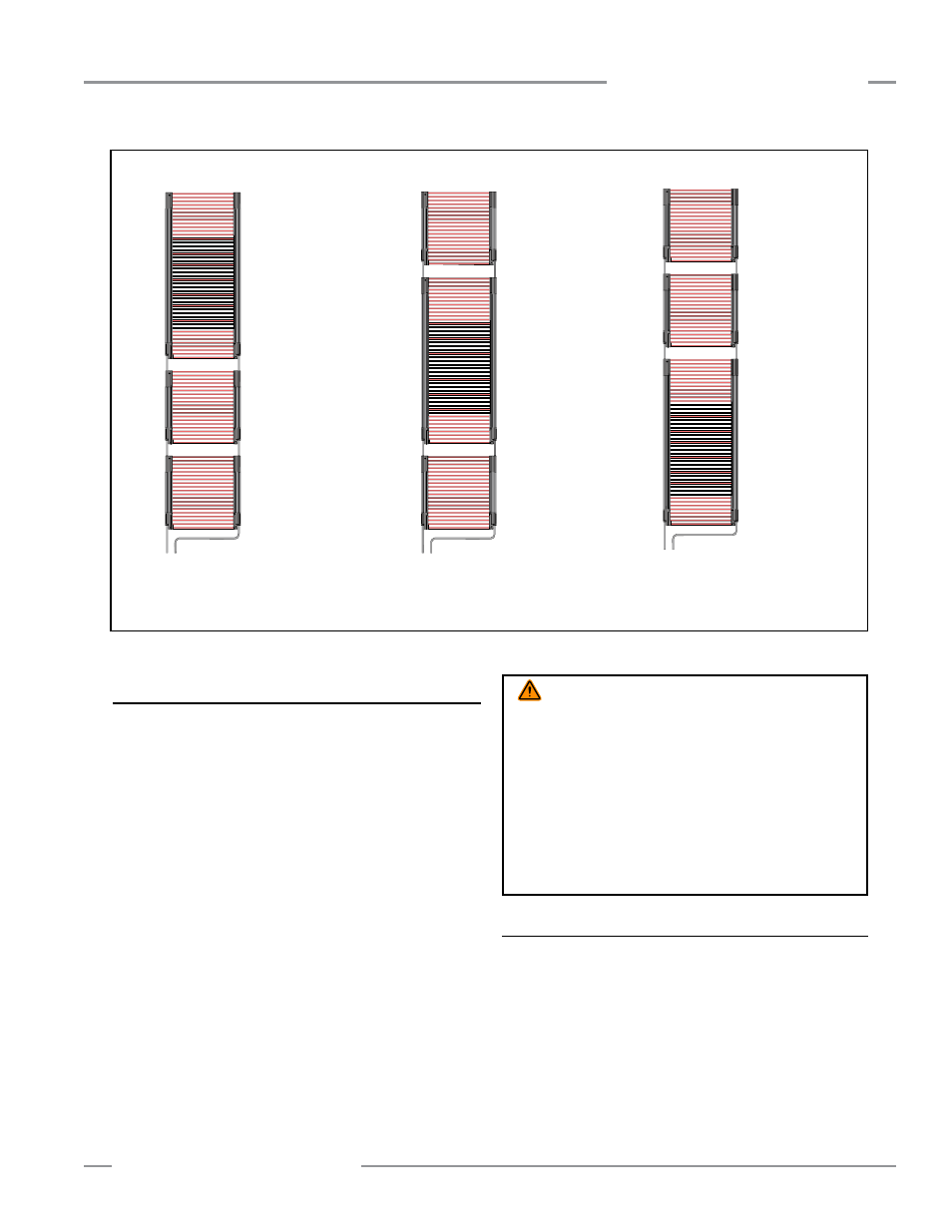
Figure 7-6. Calculating response times for a three-light screen cascade – both Individual and Overall methods
7.6 Cascaded Sensor Configuration Settings
Setting cascaded sensors for scan code, trip or latch output,
external device monitoring (EDM), reduced resolution, fixed
blanking and inverted display is identical to the procedure for
non-cascadeable emitters and receivers (see Section 4).
Scan codes for each emitter and receiver pair must match.
However, for cascaded installations, scan codes must alternate
on adjacent systems as described in Section 3.1.8 and Figure
3-10. See warning.
While the scan code, reduced resolution, fixed blanking, and
inverted display settings are independent for each cascaded
sensor pair, the trip/latch mode and EDM settings must be
determined by the first receiver in the cascade (closest to the
machine interface), which controls the OSSD outputs. All other
receivers in the cascade must be set for trip mode and
2-channel EDM (factory default settings).
The settings on the first receiver then determine trip or latch
mode and 1- or 2-channel EDM/aux. output, and this is the only
receiver that requires a reset following a latch condition.
7.6.1 Fixed Blanking
One or more areas within any cascaded EZ-SCREEN LP sensor
pair can be blanked out, just as with other EZ-SCREEN LP light
screens. Blanking for each sensor pair within a cascade, if
required, must be programmed separately. See Section 3.4.3
for more information and programming procedure.
For cascadeable models only: a standalone receiver or the
last receiver in a cascade may be configured remotely for fixed
blanking, using an EZA-RBK-1 remote key switch box or other
options as described in Section 7.10.
WARNING . . .
Scan Code
In situations where multiple systems are mounted closely
together, or where a secondary emitter is in view (within ±5°),
within range of an adjacent receiver; the adjacent systems must be
configured for different Scan Codes (i.e., one system set for Scan
Code 1 and the other for Scan Code 2).
If not, a receiver may synchronize to the signal from the
wrong emitter, reducing the safety function of the light screen.
This situation will be discovered by performing the trip test
(see Section 3.4.4).
EZ-SCREEN LP
Position #3
43.5 + 2 + 2 = 47.5
Individual Response
Time: 47.5 ms
Emitters
Receivers
EZ-SCREEN LP
Position #3
13.5 + 2 + 2 = 17.5
Individual Response
Time: 17.5 ms
Emitters
Receivers
EZ-SCREEN LP
Position #3
13.5 + 2 + 2 = 17.5
Individual Response
Time: 17.5 ms
Emitters
Receivers
EZ-SCREEN LP
Position #2
13.5 + 2 = 15.5
Individual Response
Time: 15.5 ms
EZ-SCREEN LP
Position #2
43.5 + 2 = 45.5
Individual Response
Time: 45.5 ms
EZ-SCREEN LP
Position #2
13.5 + 2 = 15.5
Individual Response
Time: 15.5 ms
EZ-SCREEN LP
Position #1
Individual Response
Time: 13.5 ms
EZ-SCREEN LP
Position #1
Individual Response
Time: 13.5 ms
EZ-SCREEN LP
Position #1
Individual Response
Time: 43.5 ms
Machine
Control
Machine
Control
Machine
Control
System Overall Response Time for all systems shown here is 43.5 + [(3 – 1) × 2 ms] = 47.5 ms