Overview, Troubleshooting and maintenance, 2 emitter error codes – Banner EZ-SCREEN Low-Profile Safety Light Curtain Systems User Manual
Page 53: 2 test mode
P/N 133487
51
Banner Engineering Corp.
•
Minneapolis, U.S.A.
www.bannerengineering.com
•
Tel: 763.544.3164
Overview
P/N 140044 rev. E
51
Banner Engineering Corp.
•
Minneapolis, U.S.A.
www.bannerengineering.com
•
Tel: 763.544.3164
EZ-SCREEN LP
Instruction Manual
Troubleshooting and Maintenance
5.1.2 Emitter Error Codes
Multiple-digit codes are sequential, followed by a pause.
Diagnostic
Display*
Error Description
Cause of Error and Appropriate Action
Emitter Error
This error can occur either due to
excessive electrical noise or due to an
internal failure.
•
Reset the emitter by either performing a reset or cycling power to the emitter (see
Section 4.3).
• If the error clears, perform the daily checkout procedure (Section 6.3) and if OK,
resume operation.
If the System fails the daily checkout procedure, replace the emitter.
• If the error continues, check the ground connection (see Section 2.3).
•
If the sensor has a good earth ground connection, check for electrical noise (see
Section 5.3).
• If the error continues, replace the emitter.
Excessive Noise Error
This error can occur due to excessive
electrical noise.
•
Reset the emitter by either performing a reset or cycling power to the emitter (see
Section 4.3).
•
If the error clears, perform the daily checkout procedure (Section 6.3) and if OK,
resume operation.
If the System fails the daily checkout procedure, replace the emitter.
• If the error continues, check the ground connection (see Section 2.3).
•
If the sensor has a good earth ground connection, check for electrical noise (see
Section 5.3).
• If the error continues, replace the emitter.
“Axx”/“cxx”,
where “xx” are
alpha-numeric
characters
Advanced Diagnostics for the purpose
of factory troubleshooting and repair;
not intended for field troubleshooting.
If advanced diagnostic codes are inadvertently displayed, toggle the Invert Display
DIP switch (to the opposite state and back, within 1 second) to return to the standard
error code display.
This indication can occur due to a potential problem with an LED and is provided
as an early warning indicator
•
Emitter LED Problem
This is NOT an error.
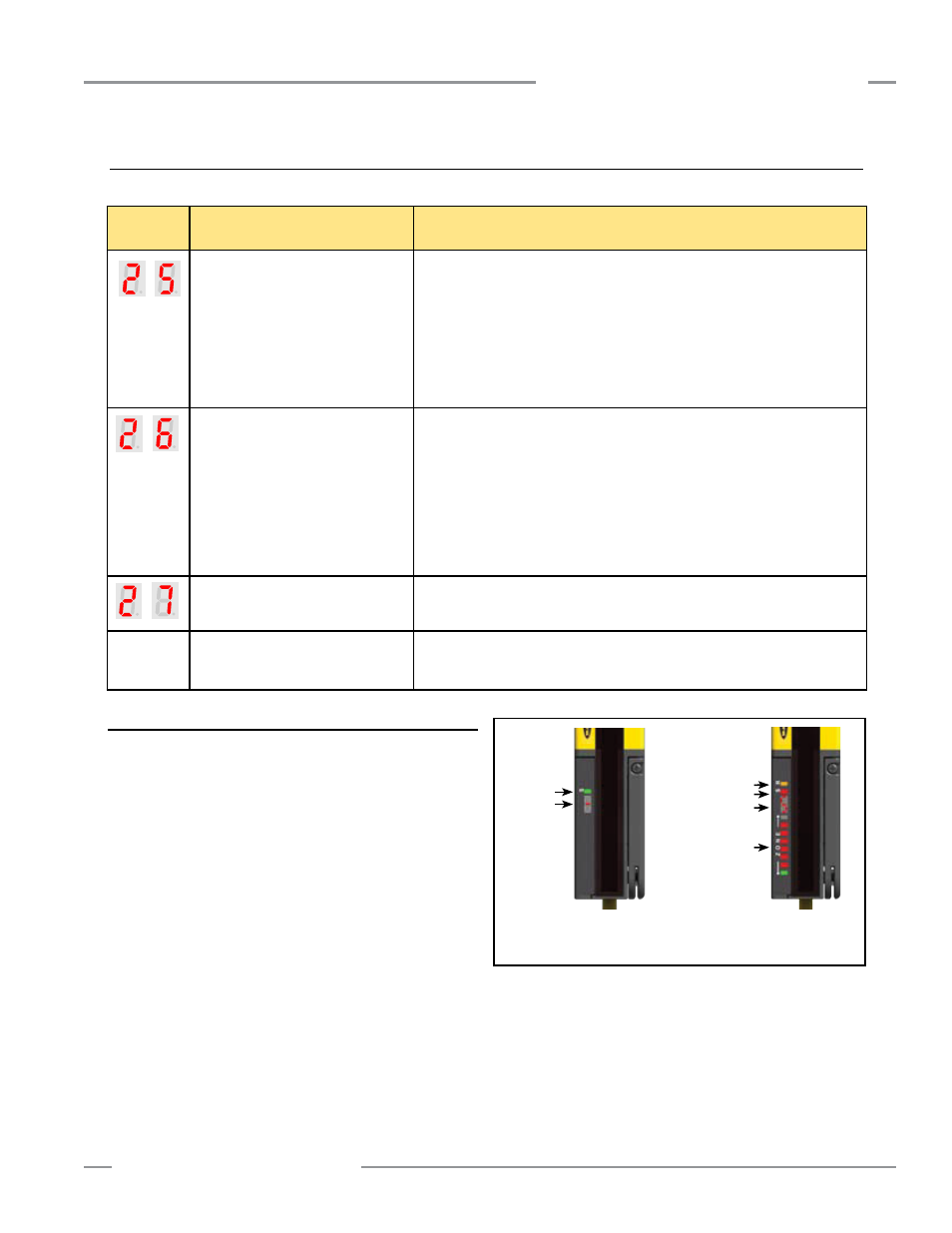
5.2 Test Mode
If System will not align or go to a Green/Clear condition, the
emitter’s Test input may be open. If so, the receiver Reset
indicator will be Yellow, all Zone indicators Red, and the Status
LED Red; the 7-segment display will show a numerical value
equal to the total number of beams, minus one. (Multiple-digit
codes are displayed sequentially.) For example, if an array has
55 beams total, the display would indicate 54. The emitter’s
Status indicator will flash Green. See Section 4.4 and Figure 5-1.
(Exception: on a 14-beam system only, the Zone 1 indicator will
be Green, and all others Red.)
Figure 5-1. TEST mode status indicators
* The 7-segment display will sequentially show a numerical value equal to one
less than the total number of beams. For example, if an array has 55 beams total,
the display would indicate 54.
Receiver
Emitter
All Red (except for
14-beam systems,
where Zone 1
indicator will be
Green)
Dash
Flashing
Green
Total number of
beams (less one)*
Yellow
Red