Overview, Installation and alignment, Warning – Banner EZ-SCREEN Low-Profile Safety Light Curtain Systems User Manual
Page 43: Channel edm 1-channel edm, Ez-screen lp instruction manual, Use of transient suppressors
P/N 133487
41
Banner Engineering Corp.
•
Minneapolis, U.S.A.
www.bannerengineering.com • Tel: 763.544.3164
Overview
P/N 140044 rev.
E
41
Banner Engineering Corp.
•
Minneapolis, U.S.A.
www.bannerengineering.com • Tel: 763.544.3164
EZ-SCREEN LP
Instruction Manual
Installation and Alignment
+24V dc
0V dc
S1
S2
Y4
Y2
14
24
34
S3
S4
Y3
Y1
13
23
33
K2
K1
Machine
Control
Feedback (optional)
MPCE
2
MPCE
1
Receiver
8-pin male
Euro-style
face view
†
IM-T-9A***
Bn (Pin #1)
Gn/Ye (#7)
Bu (#6)
Bk (#5)
Wh (#4)
Vi (#8)
Or (#3)
Or/Bk (#2)
*
*
Reset**
* Installation of transient (arc) suppressors
across the coils of MPCE1 and MPCE2 is
recommended (see Warning).
** Trip (auto reset) – Not connected
*** Other interfacing modules and solutions
available, see Section 2.3 or the
Banner Safety Catalog.
†
See Table 2.2 for further QDE-8D cable
information.
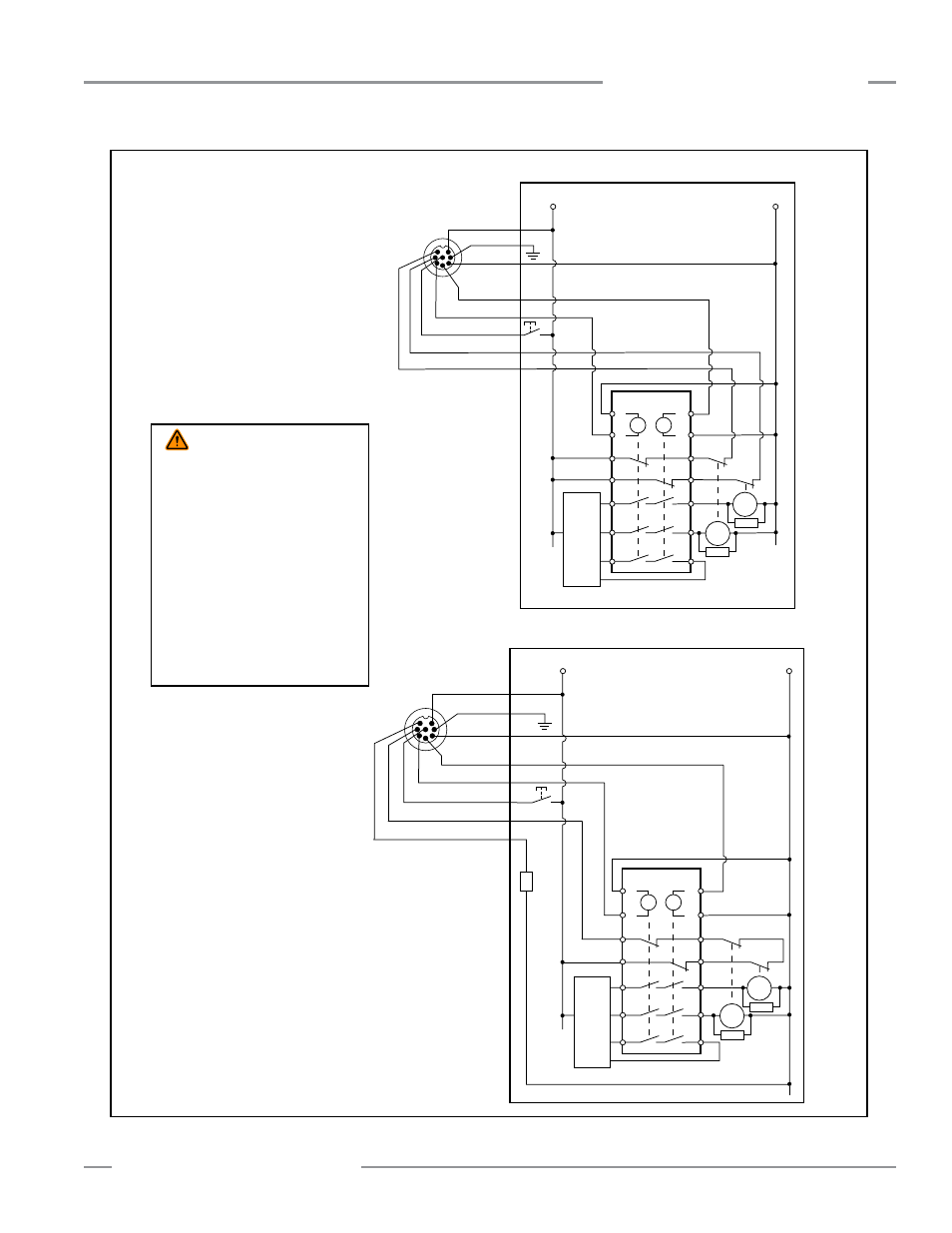
Fig ure 3-26. Generic hookup – Interface Module (1-Channel or 2-Channel EDM, manual reset)
+24V dc
+
0V dc
S1
S2
Y4
Y2
14
24
34
S3
S4
Y3
Y1
13
23
33
K2
K1
Machine
Control
Feedback (optional)
MPCE
2
MPCE
1
Receiver
8-pin male
Euro-style
face view
†
IM-T-9A***
Aux. out
Bn (Pin #1)
Gn/Ye (#7)
Bu (#6)
Bk (#5)
Wh (#4)
Vi (#8)
Or (#3)
Or/Bk (#2)
*
*
Reset**
* Installation of transient (arc) suppressors
across the coils of MPCE1 and MPCE2 is
recommended (see Warning).
** Trip (auto reset) – Not connected
*** Other interfacing modules and solutions
available, see Section 2.3 or the
Banner Safety Catalog.
†
See Table 2.2 for further QDE-8D cable
information.
2-Channel EDM
1-Channel EDM
* Installation of transient (arc) suppressors across the coils
of MPCE1 and MPCE2 is recommended (see WARNING).
** Trip (auto reset) — Not connected
*** Other interfacing modules and solutions available, see
Section 2.4 or the Banner Safety Catalog.
† See Table 2.3 for further cordset information.
WARNING . . .
Use of
Transient Suppressors
If transient suppressors are
used, they MUST be installed
across the coils of the machine
control elements. NEVER install
suppressors directly across the
contacts of the IM-T-..A Module. It
is possible for suppressors to fail as a
short circuit. If installed directly across
the contacts of the IM-T-..A Module, a
short-circuit suppressor will create an
unsafe condition.