2 how it functions, How it functions, Fig. 13: remote outputs in limit monitoring – Metrohm 781 pH/Ion Meter User Manual
Page 120
7.4 Limit monitoring
110
780/781 pH/Ion Meter, Manual
7.4.2
How it functions
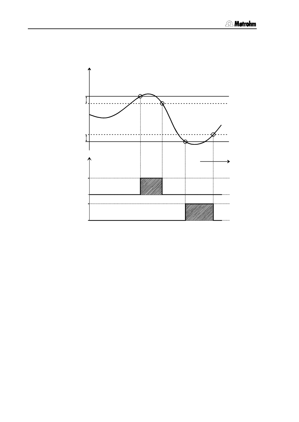
The exact way in which limit monitoring functions and the effect on the
remote outputs are shown in the following diagram.
time
measured
value
u. limit
u. hysteresis
l. hysteresis
signal output
l. limit
u. limit
l. limit
aktive
inaktive
aktive
inaktive
Fig. 13: Remote outputs in limit monitoring
The lower and upper limits and the associated hysteresis are the char-
acteristic quantities for limit monitoring. They can be defined in the pa-
rameter settings for each measuring mode (see Section 6.2 to 6.5). The
lower or upper limit is always the triggering point for the activation of the
corresponding remote line or for the message on the display. If the up-
per limit is again undercut or the lower limit exceeded again then the
activation will continue until the so-called hysteresis range has also
been exited. This avoids the too frequent activation or deactivation of
the alarm function when the measured value oscillates very closely
around a limit. This means that the activation cancellation point is de-
fined as the upper limit minus hysteresis and the lower limit plus hyste-
resis.
Set the hysteresis to zero, if you are just interested in an exact docu-
mentation of limit overruns.