Connector data, Feedback power and brake – Rockwell Automation LDAT Integrated Linear Thrusters User Manual
Page 32
32 LDAT-Series Integrated Linear Thrusters
Rockwell Automation Publication LDAT-IN001A-EN-P - August 2012
Connector Data
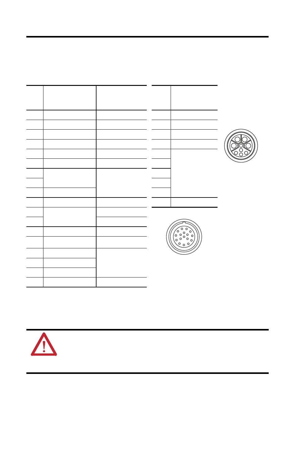
This table lists the signal descriptions for connector pins on the linear thruster.
Feedback
Power and Brake
Pin
Signal Name
LDAT-xxxxxxx-xBx
(incremental encoder)
Signal Name
LDAT-xxxxxxx-xDx
(absolute encoder)
(2)
(2)
Absolute encoder is only compatible with Kinetix 300 single-axis drives.
Pin
(3)
(3)
Power pins A, B, C, and D may be labeled as U, V, W, and GND respectively.
Reserved pins E and H may be numbered 1 or 2.
Signal Name
1
A+
Sin+
A
Phase U
2
A-
Sin-
B
Phase V
3
B+
Cos+
C
Phase W
4
B-
Cos-
D
Ground
5
Index+
Data+
E Reserved
6
Index-
Data-
F
7
Reserved
Reserved
G
8
H
9
+5V DC
L
10
Common
Common
Case
Cable Shield and GND
11
Reserved
+9V DC
12
Reserved
13
TS+
(1)
(1)
The normally closed thermal switch opens at 100 °C (212 °F).
TS+
(1)
14
TS-
(1)
TS-
(1)
15
S1
Reserved
16
S2
17
S3
Case
Shield
Shield
ATTENTION: Be sure that cables are installed and restrained to prevent uneven tension or
flexing at the cable connectors. Excessive and uneven lateral force at the cable connector may
result in damage to the housing and contacts as the cable flexes.
Failure to observe these safety precautions could result in damage to the motor and its
components.
A
C
B
D
E
H
L
F
G
Intercontec P/N
BEDC091NN00000202000
1
2
3
4
5
6
7
8
9
10
11 12
13
14
15
16
17
Intercontec P/N
AEDC113NN00000202000