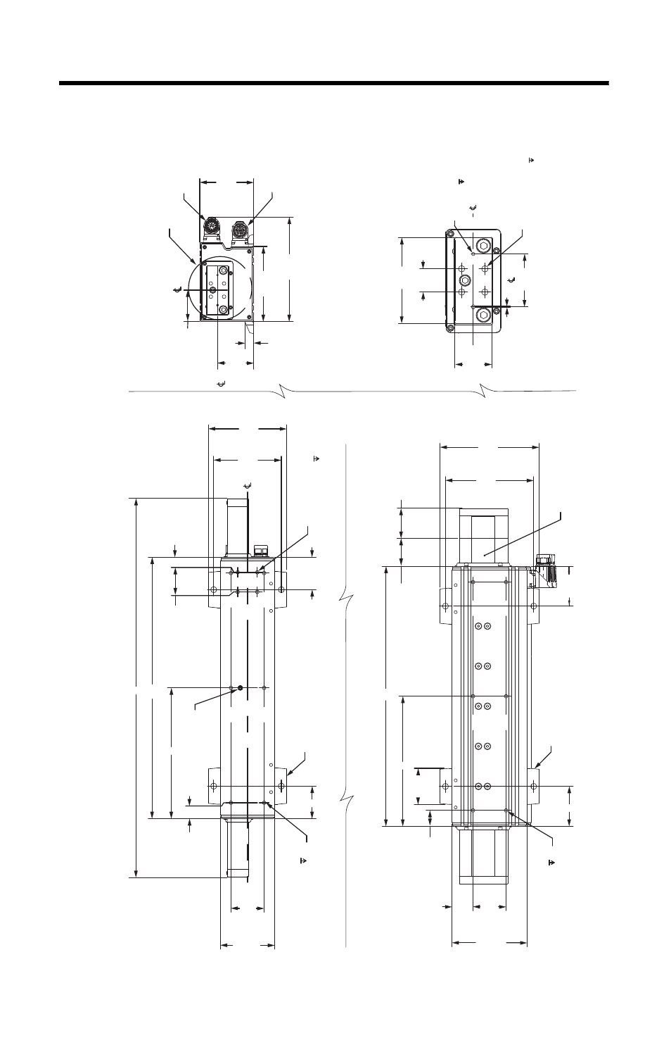
Dimensions, Li n ea r th ru st er di m ensi ons (fra m e 30) – Rockwell Automation LDAT Integrated Linear Thrusters User Manual
Page 20
20 LDAT-Series Integrated Linear Thrusters
Rockwell Automation Publication LDAT-IN001A-EN-P - August 2012
Dimensions
52.50
(2.07)
60.48
(2.38)
To
St
op
1/2 str
ok
e
Ty
pical both ends
(1)
Typical both ends
(1)
46.35
(1.82)
60.00
(2.36)
Typical
M
14.56
(0.57)
Ty
pical
A
26.35
(1.04)
Typical
90.00
(3.54)
174.03
(6.85)
55.00 (2.17)
165.00
(6.50)
125.00
(4.92)
125.00
(4.92)
Refer
enc
e
35.00 (1.38)
L
147.00
(5.79)
B
66.35
(2.612)
81.00
(3.19)
35.00
(1.38)
22.00
(0.87)
Squar
e
50.00
(1.97)
D
ow
el P
in Clear
anc
e
(2X) M3 x 6.0 (0.24)
1.00
(0.04)
D
etail A
Slider end moun
ting
ty
pical both ends
Ac
ce
ssor
y Moun
ting Holes
(4X) M6 x 1.0-6H x 9.0 (0.35)
A
26.35
(1.04)
Typical
55.00
(2.17)
C
112.00
(4.41)
130.00
(5.12)
32.50
(1.28)
Squar
e
25.10
(0.99)
M
53.85
(2.120)
90.00
(3.54)
Refer
enc
e
M6 x 1.0-6h x 7.0
Moun
ting Holes in N plac
es
.
LD
AT
-MID
-FTMOUNT optional foot
moun
ting uses (4X) M8 x1.25 x 20 min
sock
et head cap scr
ew
.
O
ptional Clevis Moun
ting Holes
(4X) M6 x 1.0-6h x 7.0
Feedback C
onnec
to
r
P
ow
er C
onnec
to
r
(1) Up t
o appr
ox
ima
tely 5 mm (0.2 in.) o
ver
tr
av
el a
t each end
. An additional 12.7 mm (0.5 in.) o
ver
tr
av
el each end when st
op is
fully c
ompr
essed in a cr
ash c
ondition.
Bott
om
Vi
ew of S
ide Mounting
Bott
om
Vi
ew of Bott
om Mounting
End
Vi
ew of Bott
om Mounting
Shipping/
Handling L
ockscr
ew
AT
TENTION:
High magnetic field
.
Us
e caution with t
ools and loose har
dw
ar
e.
Pa
cemak
er w
ear
ers main
tain
300 mm (12 in.) distanc
e.
LD
AT
-MID
-FTMOUNT optional foot
moun
ting uses (4X) M8 x 1.25 x 20, min
sock
et head cap scr
ews
.
Po
w
er and feedback
connec
to
rs can r
ota
te
180°
See
D
etail A
M6 x 1.0-6h x 7.0
Moun
ting Holesin N plac
es
D
imensions ar
e in mm (in.)
Li
n
ea
r
Th
ru
st
er Di
m
ensi
ons (fra
m
e
30)