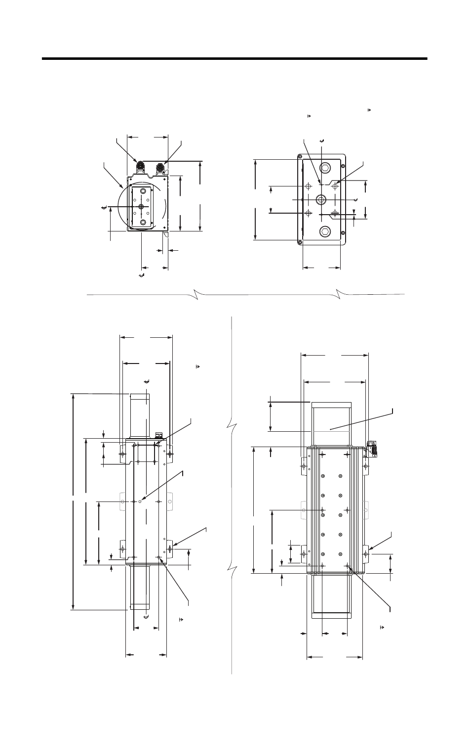
Linear thrust er d imensions (frame 100) – Rockwell Automation LDAT Integrated Linear Thrusters User Manual
Page 26
26 LDAT-Series Integrated Linear Thrusters
Rockwell Automation Publication LDAT-IN001A-EN-P - August 2012
52.70
(2.075)
18.00
(0.709)
Ty
pical
140.00
(5.512)
190.00
(7.480)
239.12
(9.414)
92.49
(3.641)
84.00
(3.307)
L
212.00
(8.346)
230.00
(9.055)
66.35
(2.612)
Typical
85.00
(3.346)
26.35
(1.037)
Typical
A
M
62.00
(2.441)
Typical
52.50
(2.067)
190.00
(7.480)
Refer
enc
e
To
St
op
1/2 str
ok
e
Ty
pical both ends
(1)
Typical both ends
(1)
AT
TENTION: High magnetic field
.
Us
e caution with t
ools and loose har
dw
ar
e.
Pa
cemak
er w
ear
ers: main
tain
300 mm (12 in.) distanc
e.
135.00
(5.315)
63.00
(2.480)
50.00
(1.969)
45.00
(1.772)
Squar
e
1.00
(0.039)
Moun
ting Holes
(4x) M8 x 1.25-6h x 12.0
D
ow
el P
in Clear
anc
e
(2x) M3 x 6.0 (0.24)
M
A
26.35
(1.037)
Typical
162.00
(6.378)
180.00
(7.087)
53.85
(2.120)
85.00
(3.346)
56.50
(2.224)
Squar
e
23.10
(0.909)
140.00
(5.512)
Refer
enc
e
M8 x 1.25-6H x 12.0
Moun
ting Holes in N plac
es
.
M8 x 1.25-6H x 12.0
Moun
ting Holes in N plac
es
.
LD
AT
-LARGE-FTMOUNT optional foot
moun
ting uses quanitit
y S M10 x 1.5 x 20 min
sock
et head cap scr
ew
.
LD
AT
-LARGE-FTMOUNT optional foot
moun
ting uses quanitit
y S M10 x 1.5 x 20 min
sock
et head cap scr
ew
.
O
ptional Clevis Moun
ting Holes
(4X) M8 x 1.25-6H x 12.0
(1) Up t
o appr
ox
ima
tely 5 mm (0.2 in.) o
ver
tr
av
el a
t each end
. An additional 12.7 mm (0.5 in.) o
ver
tr
av
el each end when st
op is
fully c
ompr
essed in a cr
ash c
ondition.
Bott
om
Vi
ew of S
ide Mounting
Bott
om
Vi
ew of Bott
om Mounting
End
Vi
ew of Bott
om Mounting
Shipping/
Handling L
ockscr
ew
Po
w
er and feedback
co
nnec
tors can r
ota
te
180°.
Se
e
D
etail A
D
etail A
Slider end moun
ting
ty
pical both ends
Feedback C
onnec
to
r
P
ow
er C
onnec
tor
Linear
Thrust
er D
imensions (frame
100)