Important – Rockwell Automation 1797-OE8 FLEX Ex Analog Modules User Manual User Manual
Page 93
Publication 1797-6.5.1 - May 2005
Specifications A-13
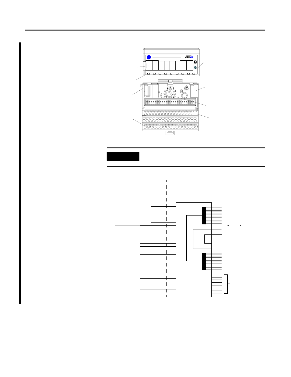
IMPORTANT
A terminal base may or may not have an I/O module
installed.
1797- OE8
Allen-Bradley
B
-
A
OUT 1
OUT 0
OUT 2
PWR
OUT 7
OUT 6
OUT 5
OUT 4
OUT 3
4
8 CHANNEL ANALOG OUTPUT
FLEX Ex Analog
Output I/O Module
LEDs
Female Bus
Connection
Field Wiring
Terminals
Terminal Base
Terminal Base
Key
Male Bus
Connection
Key Position for
Terminal Base
Insertion
42013
Hazardous (Classified) Location
Class I, Zones 0, 1, & 2 Groups IIC, IIB, IIA
Class I, Div. 1 & 2 Groups A, B, C, D
Class II, Div. 1 & 2 Groups E, F, G
Class III, Div. 1 & 2
Hazardous (Classified) Location
Class I, Zones 1 & 2 Groups IIC, IIB, IIA
Class I, Div. 1 & 2 Groups A, B, C, D
To any intrinsically safe
device or associated
apparatus with Entity
Concept parameters of
V
oc
< 5.8V; I
sc
< 400mA.
T
o any intrinsically safe
device or associated
apparatus with Entity
Concept parameters of
V
oc
< 9.5V; I
sc
< 1A.
To any IS device with Entity
Concept parameters of
(V
max
, I
max
, C
i
, L
i
) appropriate
for connection to associated
apparatus with Entity Concept
parameters listed in Table 2.
1797-OE8
16
Shield Connection Only
50
51
35
34
V
max
=5.8V
I
max
=400mA
C
i
=1350nF
L
i
=negligible
V
max
=9.5V
I
max
=1A
C
i
=negligible
L
i
=negligible
Male Bus
Connector
33
40
41
42
43
44
45
0 (+)
Female Bus
Connector
1 (-)
4 (+)
5 (-)
8 (+)
9 (-)
12 (+)
13 (-)
17 (+)
18 (-)
21 (+)
22 (-)
25 (+)
26 (-)
29 (+)
30 (-)
ch0
ch1
ch2
ch3
ch4
ch5
ch6
ch7
42016
Any Simple Apparatus or I.S.
device with Entity Concept
parameters (V
max
, I
max
, C
i
, L
i
)
appropriate for connection to
associated apparatus with
Entity Concept parameters
listed in Table 1.