Typical module calibration command word -3, Typical module calibration command word – Rockwell Automation 1797-OE8 FLEX Ex Analog Modules User Manual User Manual
Page 59
Publication 1797-6.5.1 - May 2005
Calibrating Your Module 5-3
Typical MODULE Calibration Command Word
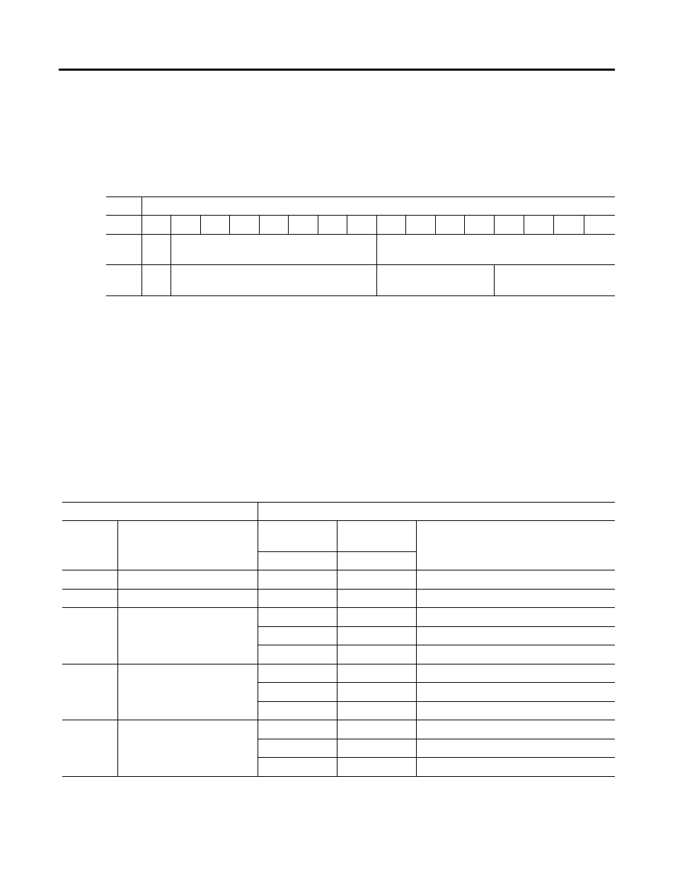
The controller sends a MODULE calibration command word over the
network, onto the flexbus and to the module.
The I/O module may do a number of things based on the particular
calibration command data sent by the controller. The table below shows the
general structure of calibration commands.
The calibration command structure instructs the module to calibrate individual
channels or to calibrate all channels at once. If all channels are to be calibrated
at once, a single calibration command is sent along with calibration command
data selecting the calibration type to be accomplished. If individual channels
are to be calibrated, again, a single calibration command is sent. The
calibration command data specifies the specific channel and calibration type to
be accomplished.
Table 5.3 Calibration Command Word
R/W
Bit
15
14
13
12
11
10
9
8
7
6
5
4
3
2
1
0
write
cmd
flag
Calibration All Channels
sub-Command 0-255
write
cmd
flag
Calibration By Channel
Channel Select 0-15
sub-Command 0-15
Table 5.4 General Calibration Command Structure
MODULE Calibration Command
MODULE Calibration Command Data
Command
Meaning
Data (up nibble)
Data (low
nibble)
Meaning
channel
command
0
Commands Idle
x
x
command method is idle
1
No Operation
x
x
no operation is required
4
General Calibration by Channel
0-7
0
zero min and max scale coefficients
0-7
1-15
not used
8-15
0-15
not used
5
Min Scale Calibration by
Channel
0-7
0
input = 1mA
0-7
1-15
not used
8-15
0-15
not used
6
Max Scale Calibration by
Channel
0-7
0
input = 21mA
0-7
1-15
not used
8-15
0-15
not used