Rockwell Automation 1797-OE8 FLEX Ex Analog Modules User Manual User Manual
Page 83
Publication 1797-6.5.1 - May 2005
Specifications A-3
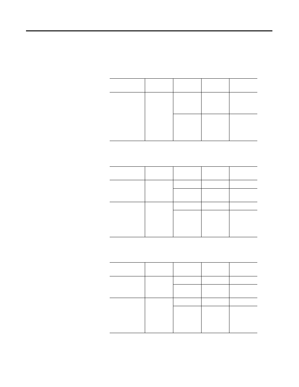
1797-IE8 and -IE8NF CE, CENELEC I/O Entity Parameters
Measurement input (sig to -) for ch 0 to ch 7 (terminals: 1-2; 5-6; 9-10;
13-14; 18-19; 22-23; 26-27; 30-31)
Source output (+ to sig) for ch 0 to ch 7 (terminals: 0-1; 4-5; 8-9; 12-13; 17-18;
21-22; 25-26; 29-30)
Source output plus measurement input (+ to -) for ch 0 to ch 7 (terminals: 0-2;
4-6; 8-10; 12-14; 17-19; 21-23; 25-27; 29-31)
Protection
Group
Allowed
Capacitance
Allowed
Inductance
U
o
= 5V
I
o
= 1mA
P
o
= 1.3mW
EEx ia
IIB
1000µF
1H
U
i
= 28V
I
i
= 93mA
C
i
and L
i
negligible
IIC
100µF
1H
Protection
Group
Allowed
Capacitance
Allowed
Inductance
U
o
= 23.7V
I
o
= 92.5mA
P
o
= 548mW
EEx ia
IIB
560nF
10mH
IIC
66nF
2.5mH
If concentrated
capacitance
and/or
inductance are
available, use the
following values.
EEx ia
IIB
320nF
10mH
IIC
60nF
2mH
Protection
Group
Allowed
Capacitance
Allowed
Inductance
U
o
= 23.7V
I
o
= 93.5mA
P
o
= 555mW
EEx ia
IIB
560nF
10mH
IIC
66nF
2.5mH
If concentrated
capacitance
and/or
inductance are
available, use the
following values.
EEx ia
IIB
320nF
10mH
IIC
60nF
2mH