Chapter 7, Troubleshooting the flex ex analog i/o modules, What this chapter contains – Rockwell Automation 1797-OE8 FLEX Ex Analog Modules User Manual User Manual
Page 77: Status indicators, What this chapter contains -1 status indicators -1, 1797-ie8 and -ie8nf modules -1, Chapter
1
Publication 1797-6.5.1 - May 2005
Chapter
7
Troubleshooting the FLEX Ex
Analog I/O Modules
What this Chapter Contains
Read this chapter to troubleshoot your I/O module.
Status Indicators
1797-IE8 and -IE8NF Modules
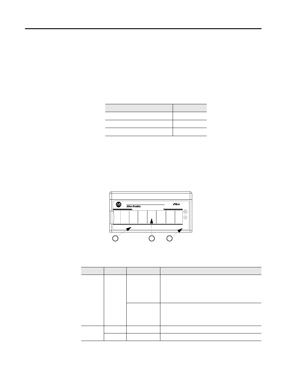
The 1797-IE8 and -IE8NF modules have one power indicator that is on when
power is applied to the module and one status indicator for each input.
For information on:
See page:
Indicator
Color
State
Meaning
Status
Red
On
At power up – Channel 0 indicator lights at powerup until
all internal diagnostics are checked. After successful
powerup, the indicator goes off if no fault is present.
After successful powerup – Indicates a critical fault
(diagnostic failure, etc.)
Blinking (when
faults are
enabled, and bit
set)
Indicates a noncritical channel fault
Power
Off
Module not powered
Green
On
Module receiving power
Ex
PWR
1797-IE8
8 CHANNEL ANALOG INPUT
IN1
IN0
IN2
IN3
IN4
IN5
IN6
IN7
3
40070
A
B
C
A = Status indicators
B = Insertable labels for writing individual input designations
C = Power indicator