Grounding the module, Chapter summary, Grounding the module -14 chapter summary -14 – Rockwell Automation 1797-OE8 FLEX Ex Analog Modules User Manual User Manual
Page 48
Publication 1797-6.5.1 - May 2005
3-14 How to Install Your FLEX Ex Analog Modules
Table 3.3 Wiring connections for the 1797-OE8 Module
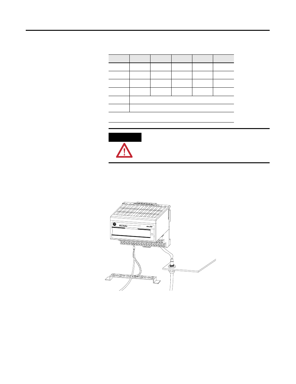
Grounding the Module
All I/O wiring must use shielded wire. Shields must be terminated external to
the module, such as bus bars and shield-terminating feed throughs.
Chapter Summary
In this chapter, we told you how to install your input module in an existing
programmable controller system and how to wire to the terminal base units.
Move to chapter 4 to learn about input, output and configuration files for the
analog I/O modules on ControlNet.
Output
Output + Output –
Output
Output + Output –
Output 0
A-0
A-1
Output 4
B-17
B-18
Output 1
A-4
A-5
Output 5
B-21
B-22
Output 2
A-8
A-9
Output 6
B-25
B-26
Output 3
A-12
A-13
Output 7
B-29
B-30
+V
Terminals 34 and 50
-V
Terminals 35 and 51
Terminals 16, 33, 40, 41, 42, 43, 44 and 45 are connected to chassis ground.
ATTENTION
Do not use the unused terminals on the terminal base unit.
Using these terminals as supporting terminals can result in
damage to the module and/or unintended operation of
your system.
30820