Chapter summary, Chapter summary -10 – Rockwell Automation 1797-OE8 FLEX Ex Analog Modules User Manual User Manual
Page 66
Publication 1797-6.5.1 - May 2005
5-10 Calibrating Your Module
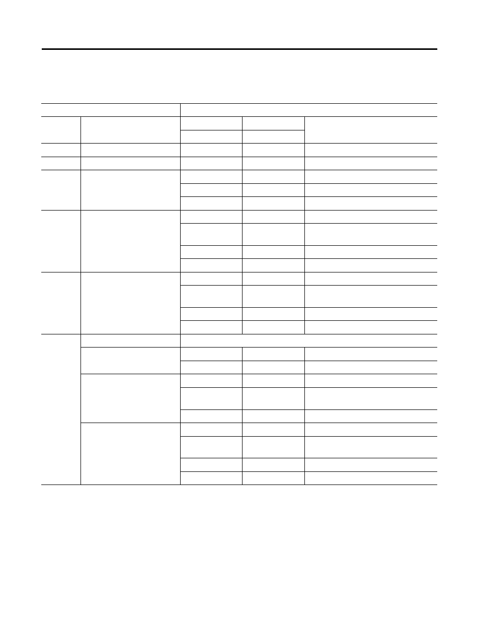
The following table shows the calibration MODULE command definitions.
Chapter Summary
In this chapter, you learned how to calibrate your FLEX Ex analog I/O
modules. Move to Chapter 6 to see how to apply FLEX Ex analog I/O
modules.
Table 5.9 Calibration MODULE Command Definitions
MODULE Calibration Command
MODULE Calibration Command Data
Command
Meaning
Data (up nibble)
Data (low nibble)
Meaning
channel
command
0
Commands Idle
x
x
command method is idle
1
No Operation
x
x
no operation is required
4
General Calibration by Channel
0-7
0
zero min scale and max scale coefficients
0-7
1-15
not used
8-15
0-15
not used
5
Min Scale Calibration by
Channel
0-7
0
output = 1mA
0-7
1
accept value in channel data word as min
scale calibration
0-7
2-15
not used
8-15
0-15
not used
6
Max Scale Calibration by
Channel
0-7
0
output = 21mA
0-7
1
accept value in channel data word as max
scale calibration
0-7
2-15
not used
8-15
0-15
not used
36
Calibration all Channels
General Calibration all Channels
0
0
zero min scale and max scale coefficients
0
1-15
not used
Min Scale Calibration all
Channels
1
0
output = 1mA
1
1
accept values in channel data words as min
scale calibration
1
2-15
not used
Max Scale Calibration all
Channels
2
0
output = 21mA
2
1
accept values in channel data words as
max scale calibration
2
2-15
not used
3-15
0-15
not used