Important – Rockwell Automation 1797-OE8 FLEX Ex Analog Modules User Manual User Manual
Page 88
Publication 1797-6.5.1 - May 2005
A-8 Specifications
IMPORTANT
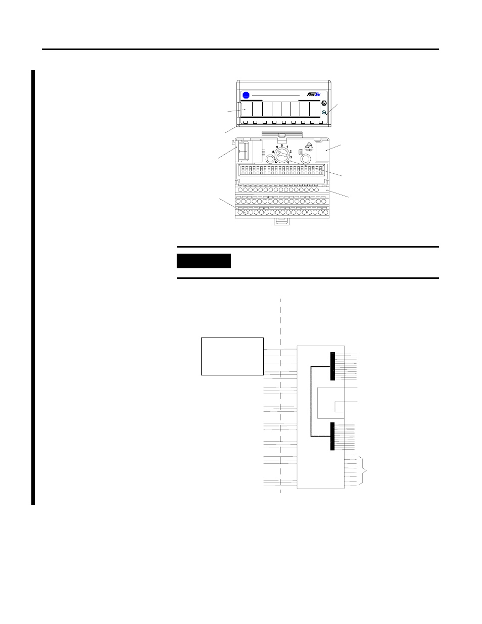
A terminal base may or may not have an I/O module
installed.
1797- IE8
Allen-Bradley
B
-
A
7
PWR
0
1
2
3
4
5
6
3
8 CHANNEL ANALOG INPUT
FLEX Ex Analog Input
I/O Module
LEDs
Female Bus
Connection
Field Wiring
Terminals
Terminal Base
Terminal Base
Key
Male Bus
Connection
Key Position for
Terminal Base
Insertion
42055
Hazardous (Classified) Location
Class I, Zones 0 Groups IIC
Class I, Div. 1 Groups A, B, C, D
Class II, Div. 1 Groups E, F, G
Class III, Div. 1
Hazardous (Classified) Location
Class I, Zones 1 Groups IIC
Class I, Div. 1 Groups A, B, C, D
For connection to other
modules, refer to the
General FM Certification
Information on page
29-1 in 1797-6.5.6.
From FM approved
devices, 1797-PS2N.
For connection to other
modules, refer to the
General FM Certification
Information on page 29-1 in
1797-6.5.6.
16
Shield Connection Only
50
51
35
34
V
max
=5.8V
I
max
=400mA
C
i
=1350nF
L
i
=negligible
V
max
=9.5V
I
max
=1A
C
i
=negligible
L
i
=negligible
Male Bus
Connector
33
40
41
42
43
44
45
0 (+)
Female Bus
Connector
Any Simple Apparatus or FM
approved device with Entity
Concept parameters (V
max
, I
max
,
C
i
, L
i
) appropriate for connection
to associated apparatus with
Entity Concept parameters listed
in Table 1.
1 (sig)
ch0
ch1
ch2
ch3
ch4
ch5
ch6
ch7
2 (-)
4 (+)
5 (sig)
6 (-)
8 (+)
9 (sig)
10 (-)
12 (+)
13 (sig)
14 (-)
17 (+)
18 (sig)
19 (-)
21 (+)
22 (sig)
23 (-)
25 (+)
26 (sig)
27 (-)
29 (+)
30 (sig)
31 (-)
42056
1797-IE8 or
1797-IE8NF