Rockwell Automation 1797-OE8 FLEX Ex Analog Modules User Manual User Manual
Page 46
Publication 1797-6.5.1 - May 2005
3-12 How to Install Your FLEX Ex Analog Modules
For Two-Wire Transmitter Devices
1. Connect the individual input wiring to (+) terminals (0, 4, 8, 12) on the
0-15 row (A) and on the 16-33 row (B) (terminals 17, 21, 25, 29) as
indicated in the table below.
2. Connect the associated input to the corresponding (sig) terminal (1, 5, 9,
13) on the 0-15 row (A), and on the 16-33 row (B) (terminals 18, 22, 26,
30) for each input as indicated in the table below.
3. Connect +V dc power to terminal 34 on the 34-51 row (C).
4. Connect -V to terminal 35 on the 34-51 row (C).
5. If continuing power to the next terminal base unit, connect a jumper
from terminal 50 (+V) on this base unit to terminal 34 on the next base
unit.
6. If continuing common to the next terminal base unit, connect a jumper
from terminal 50 (-V) on this base unit to terminal 35 on the next base
unit.
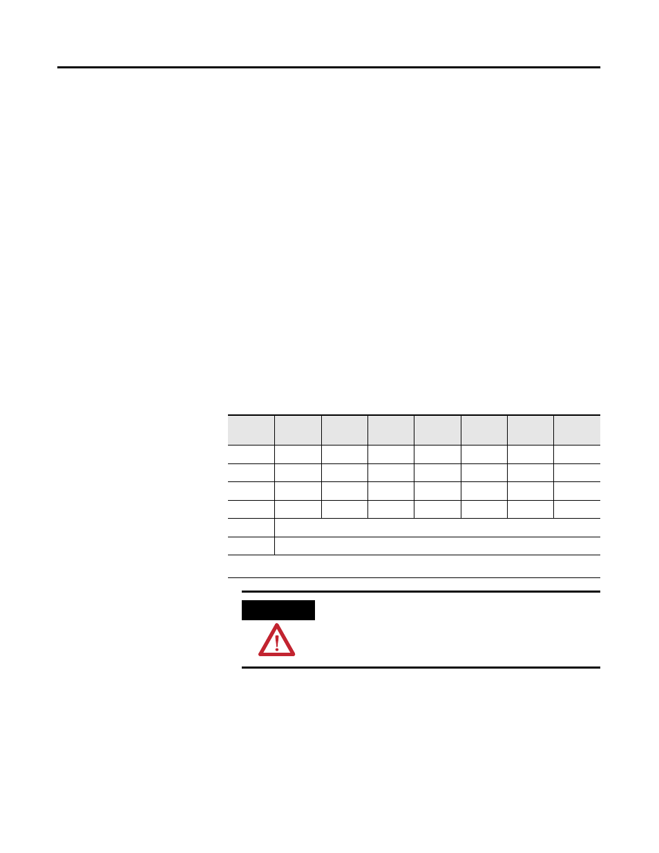
Table 3.2 Wiring connections for the 1797-IE8 and -IE8NF Modules
Input
Input
Source
Input
Signal
Input
Return
Input
Input
Source
Input
Signal
Input
Return
Input 0
A-0
A-1
A-2
Input 4
B-17
B-18
B-19
Input 1
A-4
A-5
A-6
Input 5
B-21
B-22
B-23
Input 2
A-8
A-9
A-10
Input 6
B-25
B-26
B-27
Input 3
A-12
A-13
A-14
Input 7
B-29
B-30
B-31
+V
Terminals 34 and 50
-V
Terminals 35 and 51
Terminals 16, 33, 40, 41, 42, 43, 44 and 45 are connected to chassis ground.
ATTENTION
Do not use the unused terminals on the terminal base unit.
Using these terminals as supporting terminals can result in
damage to the module and/or unintended operation of
your system.