I/o structure, Module i/o mapping -4, I/o structure -4 – Rockwell Automation 1797-OE8 FLEX Ex Analog Modules User Manual User Manual
Page 52: Module i/o mapping
Publication 1797-6.5.1 - May 2005
4-4 Input, Output, and Configuration Files for the Analog I/O Modules on the ControlNet Network
Unscheduled messaging on a ControlNet network is non-deterministic. Your
application and your configuration–number of nodes, application program,
NUT, amount of scheduled bandwidth used, etc.–determine how much time
there is for unscheduled messaging.
Module I/O Mapping
The I/O map for a module is divided into read words and write words. Read
words consist of input and status words, and write words consist of output
and configuration words. The number of read words or write words can be 0
or more.
The length of each I/O module’s read words and write words vary in size
depending on module complexity. Each I/O module will support at least 1
input word or 1 output word. Status and configuration are optional, depending
on the module.
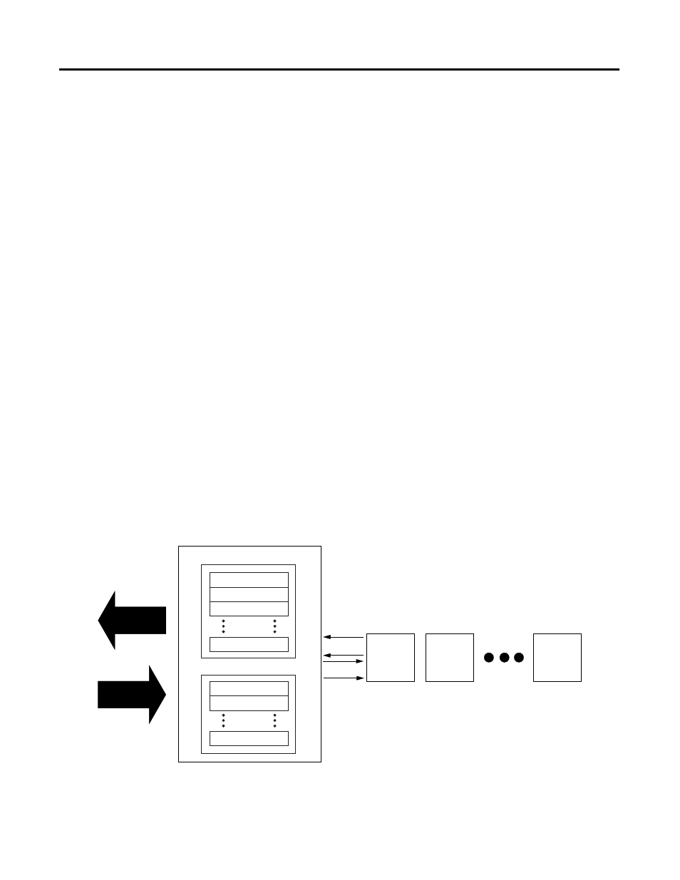
I/O Structure
Output data is received by the adapter in the order of the installed I/O
modules. The output data for slot 0 is received first, followed by the output
data for slot 1, and so on up to slot 7.
The first word of input data sent by the adapter is the Adapter status word.
This is followed by the input data from each slot, in the order of the installed
I/O modules. The input data from slot 0 is first after the status word, followed
by input data from slot 1, and so on up to slot 7.
ControlNet Adapter
Read Data
Adapter Status
Slot 0 Input Data
Slot 1 Input Data
Slot 7 Input Data
Slot 0 Output Data
Slot 1 Output Data
Slot 7 Input Data
Write
Read
I/O
Module
Slot 0
I/O
Module
Slot 1
I/O
Module
Slot 7
Network READ
Network WRITE
41628