Physical features of your analog i/o module, Using alarms on the 1797-ie8 and -ie8nf modules, Physical features of your analog i/o module -3 – Rockwell Automation 1797-OE8 FLEX Ex Analog Modules User Manual User Manual
Page 13: Indicators -3, Using alarms on the 1797-ie8 and -ie8nf modules -3, Indicators
Publication 1797-6.5.1 - May 2005
About the FLEX Ex Analog Modules 1-3
Physical Features of Your
Analog I/O Module
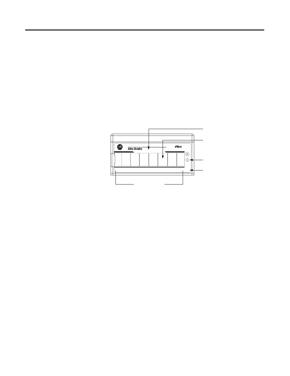
The module label identifies the keyswitch position, wiring and module
type. Use the removable label to note individual designations per
your application.
Indicators
Indicators are provided to identify input or output fault conditions, and to
show when power is applied to the module. For example, the 1797-IE8
module is shown below.
Using Alarms on the
1797-IE8 and -IE8NF
Modules
The 1797-IE8 and -IE8NF FLEX Ex modules are capable of generating four
alarms:
• Underrange
• Overrange
• Remote Fault
• Local Fault
These alarm conditions are described in general terms and as they relate to bits
on the FLEX Ex I/O module on the following pages. The following graphic
shows at what values these alarms are generated for Data Format 4.
Ex
PWR
1797-IE8
8 CHANNEL ANALOG INPUT
IN1
IN0
IN2
IN3
IN4
IN5
IN6
IN7
3
40070
1797-IE8
Module Type
Removable Label
Keyswitch Position
Indicator (#3)
Power On Indicator
Input Designators