Repair, Chapter summary, 1797-oe8 module -2 – Rockwell Automation 1797-OE8 FLEX Ex Analog Modules User Manual User Manual
Page 78: Repair -2 chapter summary -2
Publication 1797-6.5.1 - May 2005
7-2 Troubleshooting the FLEX Ex Analog I/O Modules
1797-OE8 Module
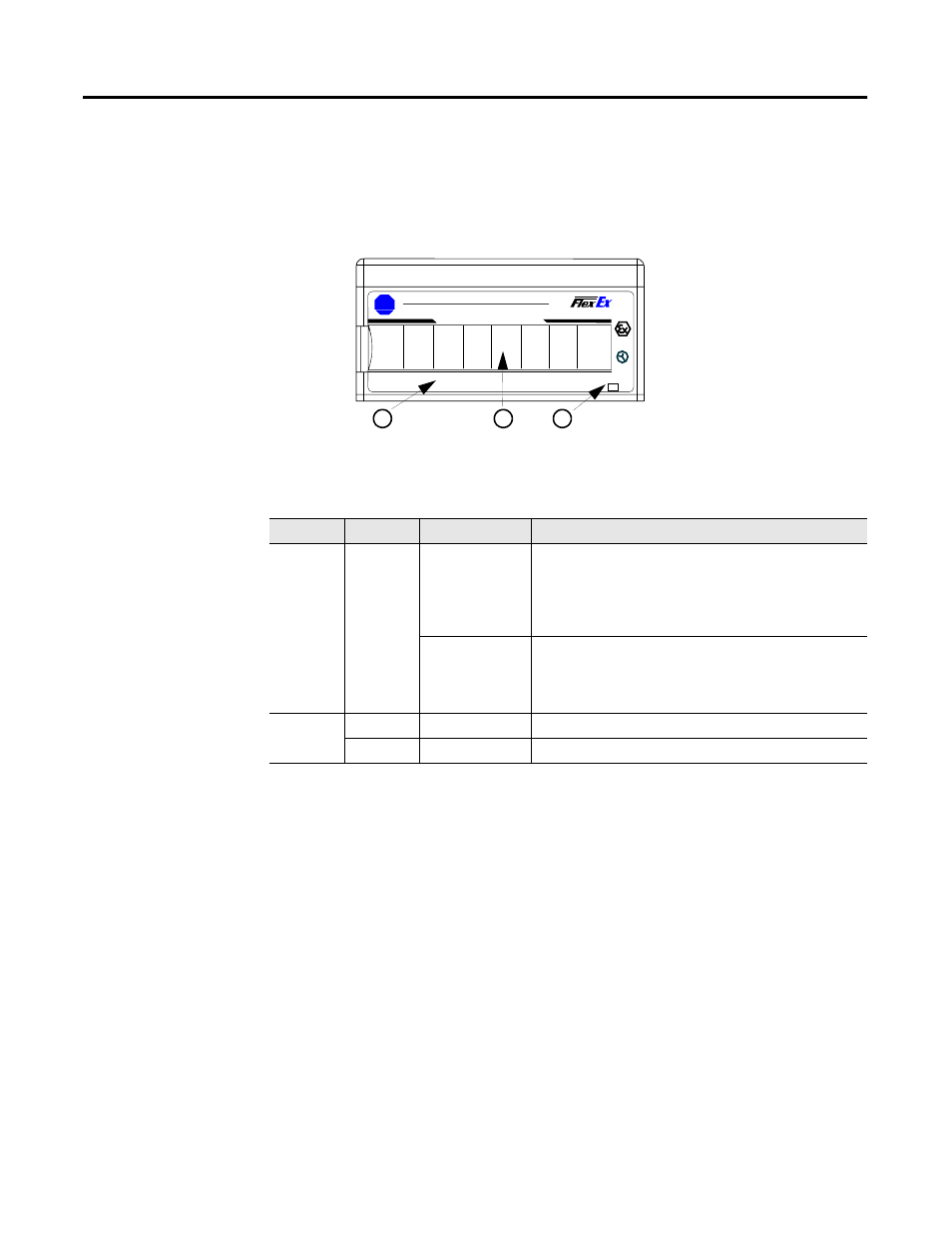
The 1797-OE8 module has one power that is on when power is applied to the
module and one status indicator for each input.
Repair
This module is not field repairable. Any attempt to open this module will void
the warranty and IS certification. If repair is necessary, return this module to
the factory.
Chapter Summary
In this chapter you learned how to troubleshoot the FLEX Ex analog I/O
modules. Move to Appendix A to see the specifications for your module.
Indicator
Color
State
Meaning
Status
Red
On
At power up – Channel 0 indicator lights at powerup until
all internal diagnostics are checked. After successful
powerup, the indicator goes off if no fault is present.
After successful powerup – Indicates a critical fault
(diagnostic failure, etc.)
Blinking (when
faults are
enabled, and bit
set)
Indicates a noncritical channel fault
Power
Off
Module not powered
Green
On
Module receiving power
1797- OE8
Allen-Bradley
B
-
A
OUT 1
OUT 0
OUT 2
PWR
OUT 7
OUT 6
OUT 5
OUT 4
OUT 3
4
8 CHANNEL ANALOG OUTPUT
41442
A
B
C
A = Status indicators
B = Insertable labels for writing individual input designations
C = Power indicator