Loop functionality verification – Rockwell Automation 1797-OE8 FLEX Ex Analog Modules User Manual User Manual
Page 70
Publication 1797-6.5.1 - May 2005
6-4 Applying FLEX Ex Analog I/O Modules
1797-IE8 and -IE8NF Functional and IS Parameters
The figure below provides data, on the Flex Ex analog input modules, which
can be matched to this transmitter.
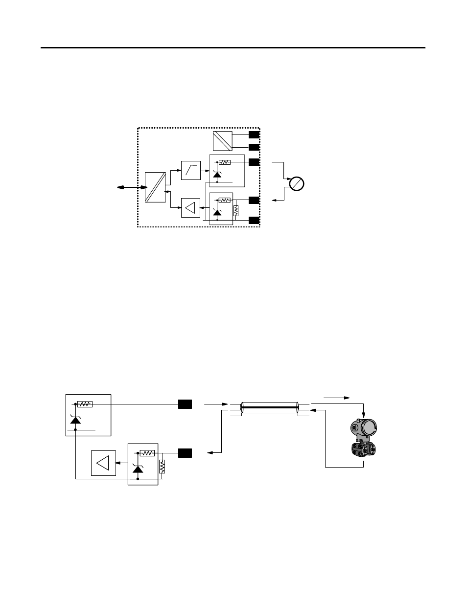
Loop Functionality Verification
The functional characteristics will be checked first. The figure below shows the
general situation which must be analyzed for proper loop function.
On the left are the module components of the voltage source to run the loop
and its internal source resistance. In the center is the cable. It represents a loss
with regard to its resistance. Cable resistance is a function of cable length. On
the right is the transmitter, which has a minimum voltage it must see to
function properly.
I
Analog Input
V>17V at I=0mA
V>15.5 at I=20mA
V>15V at I=22mA
0-22mA Measurement Range
EEx ia/ib IIB/IIC T4
Uo<23.7V
Io<92.5mA
Flexbus
41662
IIB
Ca=560nF
La=10mH
IIC
Ca=66nF
La=2.5mH
P
+
-V
sig
–
+V
4-20mA
Xmit
91
Ω
17V
22
Ω
Bus
uC
Ci<10pF/m
Li<0.5uH/m
R<0.1
Ω/m
41664
IIB
Ca=560nF
La=10mH
transmitter
minimum
voltage=10.5V
+
–
cable resistance loss
–
+
module source voltage=17V
module source resistance=91
Ω
+
sig
22
Ω
module sense
resistance=22
Ω
91
Ω
17V