5ć22 – Rockwell Automation 6008-SV2R VMEbus remote I/O Scanner User Manual
Page 73
Chapter
Operating in SVĆCompatible Mode
5
5Ć22
The VME master processor writes 21 (hex) to the command byte. There
are no input parameters from the VME master processor. The scanner
writes these parameters to the selected channel’s general data area:
Byte Offset Parameter Description
11F
scan list length
READ ONLY
The scan list length indicates the number of entries in the scan
list. The scan list length is an 8Ćbit quantity that the scanner
writes to the length of data byte in the control/status area. You
can enter a scan list length of 0.
120
I/O adapter status word block
READ ONLY
This word block contains four 16Ćbit entries (4 words) for each
adapter - 16 bits for each starting group per adapter (maximum
of 8 groups of entries). See Figure 5.10 and Figure 5.11.
160
scan list
READ ONLY
This list is a maximum of 64 bytes long. The list contains one
byteĆsized entry for each adapter in the scan list, but it contains
only 16 distinct physical adapter addresses. An adapter can
appear in the list multiple times. See Figure 5.12 on
page 5Ć24.
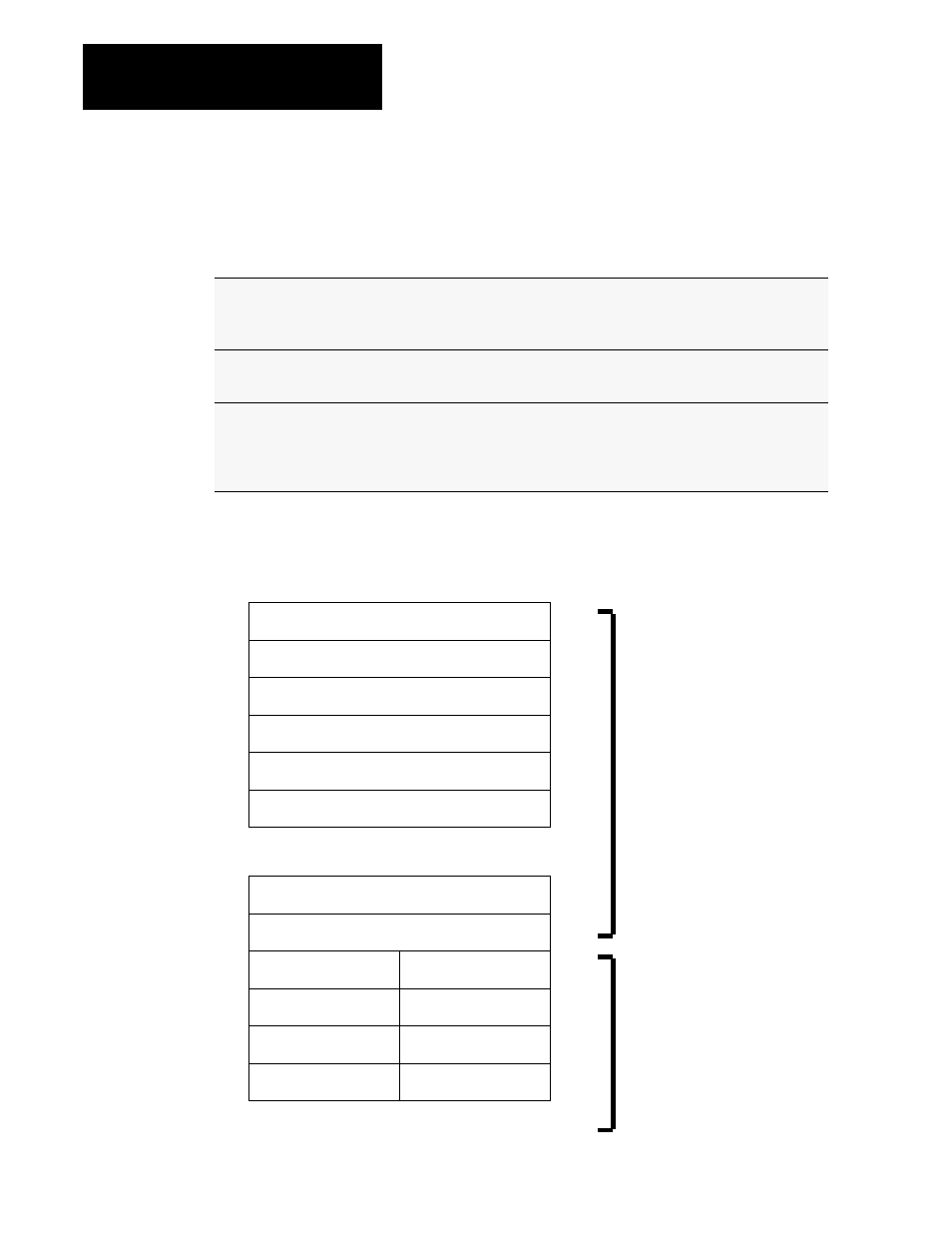
Figure 5.10
Format of the I/O adapter status word block and scan list
Each block represents 1 word. Only those
words representing starting groups of
existing racks should contain the data
described in Figure 5.11.
rack 0, starting group 0
rack 0, starting group 2
rack 0, starting group 4
rack 0, starting group 6
rack 1, starting group 0
rack 1, starting group 2
rack 7, starting group 4
●
●
●
●
rack 7, starting group 6
up to as many
as 64 bytes
rack 0, staring group 2 rack 1, starting group 2
●
●
●
●
160
162
164
166
161
163
165
167
rack 2, staring group 2 rack 3, starting group 0
rack 4, staring group 0 rack 5 starting group 2
rack 6, staring group 0 rack 7, starting group 4
121
123
125
127
129
12B
15D
15F
120
122
124
126
128
12A
15C
15E
Byte
offset
Byte
offset
channel A
adapter status words
channel A
example scan list
Each block represents 1 byte.
See Figure 5.12.
parameters