Rockwell Automation 6008-SV2R VMEbus remote I/O Scanner User Manual
Page 11
Chapter
Scanner Overview
1
1Ć3
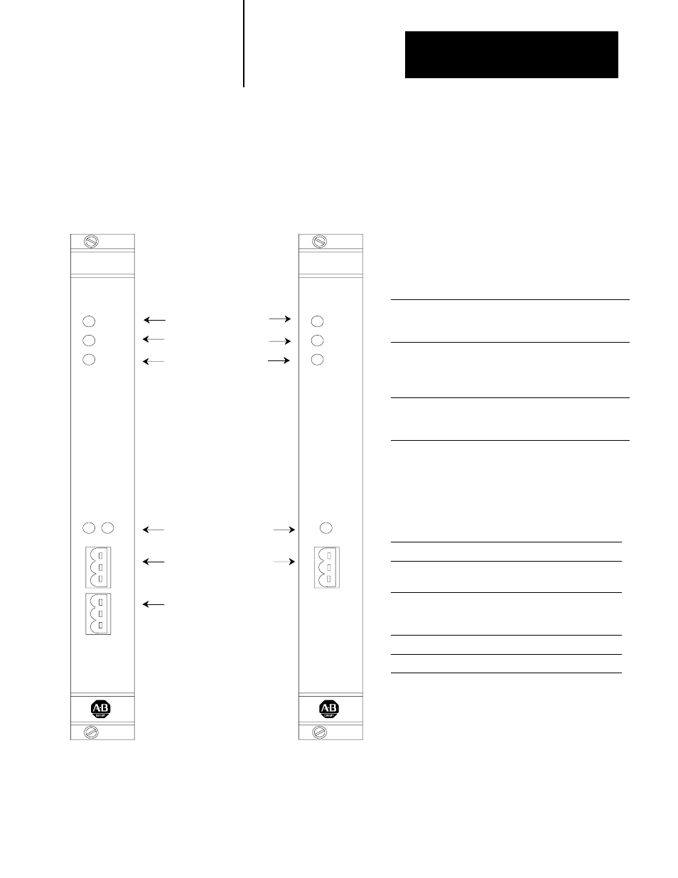
Each scanner channel supports as many as 32 physical adapters (16 logical
racks). Figure 1.2 shows the front panels of the scanners.
Figure 1.2
Scanner front panel
Table 1.A
Significance of scanner indicators
When this
indicator:
is:
it means:
PWR
(power)
green LED
illuminated
power is applied to the
module
BPLN COM
(backplane
communication)
green LED
illuminated for
approximately
a half second
a VMEbus access is made
to the scanner board
FLT
(fault)
red LED
illuminated
the scanner board is reset,
performing a self test, or a
fault has been detected
Table 1.B
Significance of channel status
indicators
When the status
indicator is:
the scanner:
off
is off line
green
is on line, in Run mode, and
scanning the racks in the scan list
blinking green
is on line, in Run mode, and
scanning only some of the racks in
the scan list
red
has an unrecoverable fault
blinking red
has a recoverable fault
Indicators:
power (green)
VMEbus backplane
communication (green)
fault (red)
Indicators:
channel status (green/red)
Channels:
remote I/O channel A
communication port
(factory enabled)
remote I/O channel B
communication port
(factory disabled)
6008ĆSV2R
PWR
BPLN
COM
FLT
6008ĆSV2R
A
B
6008ĆSV1R
PWR
BPLN
COM
FLT
6008ĆSV1R
A