Rockwell Automation 6008-SV2R VMEbus remote I/O Scanner User Manual
Page 25
Chapter
Installing the Scanner
2
2Ć6
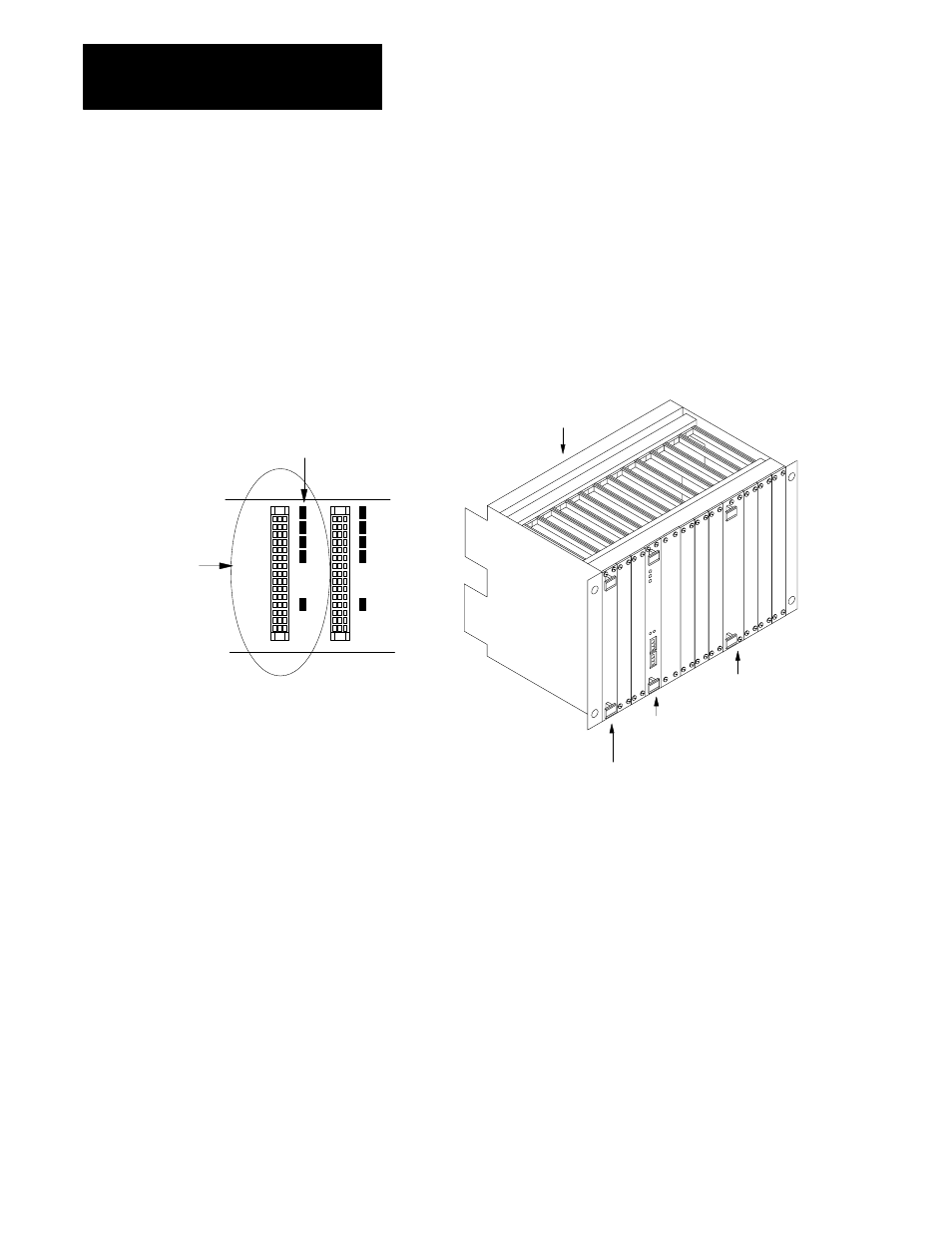
The VMEbus has several daisy-chained control signals. Almost all
VMEbus backplanes contain jumpers for these control signals to allow
systems to operate with empty slots. There are five jumpers per VME
slot, one for each of the four bus-grant arbitration levels and one for the
interrupt-acknowledge daisy chain.
Depending on the backplane manufacturer, the jumpers can be on the
rear pins of the J1 connector or alongside it on the front of the backplane.
The scanner uses 1 slot of the VME backplane. Remove these jumpers
from the slot where you plan to insert the scanner.
remove all the backplane
jumpers in the slot where
you insert the scanner
one empty slot
(jumpers are installed)
backplane
CPU
other VME module
scanner
Allen-Bradley makes specific recommendations for properly grounding its
racks so that their operation is as safe and error-free as possible. VME
systems, on the other hand, may have no formal specifications for
grounding the VME chassis frame. Allen-Bradley recommends that you
ground the VME chassis frame and that you connect the logic ground
(common) of the VME power supply to the chassis frame’s earth ground.
The specific procedure for grounding a VME chassis varies depending on
the style of the chassis. Read the Programmable Controller Wiring and
Grounding Guidelines, publication 1770-4.1, for information on how
Allen-Bradley racks are grounded, and try to ground your VME chassis
frame in a similar way.
Removing VME
Backplane Jumpers
Grounding the VME Chassis