Designing a remote i/o link, Link design guidelines – Rockwell Automation 6008-SV2R VMEbus remote I/O Scanner User Manual
Page 40
Chapter
Communicating with Remote I/O
4
4Ć3
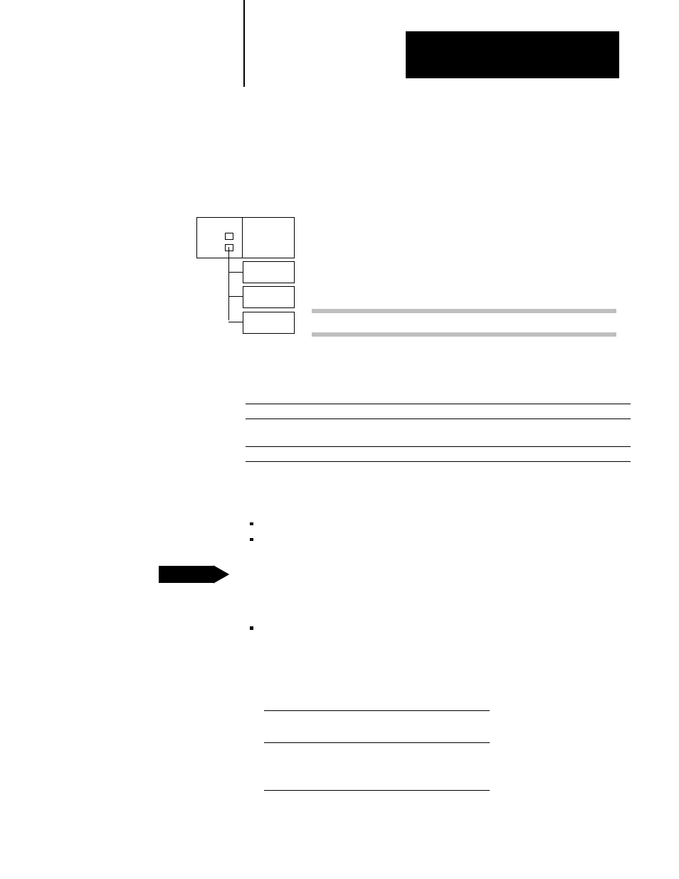
The scanner keeps a list of all of the devices connected to each channel.
Figure 4.2 shows an example scan list for one channel.
Figure 4.2
Example scan list
SV2R
Rack 1
Rack 2
Rack 3
Ch A
Ch B
Ch B Scan List
Rack
Address
Starting
Group
Rack
Size
Range
1
2
3
0
0
0
Full
1/2
Full
010Ć017
020Ć023
030Ć037
In this example, channel B continually scans the three racks in its scan list.
The steps for setting up a remote I/O system are:
Step: See:
1. configure the remote I/O adapter devices
the device's user manual
2. layout and connect the remote I/O link cable
•
page 4Ć3 for design
•
your adapter's installation information
3. specify a scan list
page 4Ć5
Designing a remote I/O link requires applying:
remote I/O link design guidelines
cable design guidelines
Link Design Guidelines
Keep these rules in mind as you design remote I/O links:
All devices connected to a remote I/O link must communicate using the
same communication rate. The rate you choose depends on the VME
operating mode:
This VME operating mode: supports these
communication rate:
SV compatible
57.6 kbps
115.2 kbps
SV superset
57.6 kbps
115.2 kbps
230.4 kbps
Designing a Remote I/O Link
Design Tip