Choosing an addressing mode – Rockwell Automation 6008-SV2R VMEbus remote I/O Scanner User Manual
Page 32
Chapter
Addressing I/O
3
3Ć3
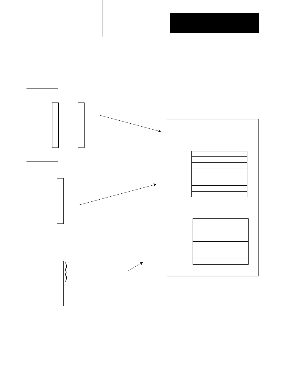
For each chassis in your I/O system, you must define how many I/O
chassis slots make up an I/O group (one word each in the input image table
and output image table); this choice is the chassis’ addressing mode.
Choose from among these available modes:
2Ćslot addressing
2 I/O chassis slots = 1 I/O group = 1 input image word and 1 output image word =
16 input bits and 16 output bits.
1Ćslot addressing
1 I/O chassis slot = 1 I/O group = 1 input image word and 1 output image word =
16 input bits and 16 output bits.
1/2Ćslot addressing
1/2 of an I/O chassis slot = 1 I/O group = 1 input image word and 1 output image word =
16 input bits and 16 output bits.
x
x
x
x
x
x
x
x
Output Image Table
Word #
Input Image Table
Word #
16 bits input
16 bits output
16 bits input and 16 bits output
16 bits input and 16 bits output
ЙЙЙЙЙЙЙЙЙ
ЙЙЙЙЙЙЙЙЙ
ЙЙЙЙЙЙЙЙ
ЙЙЙЙЙЙЙЙ
scanner memory
Rack x
x
x
x
x
x
x
x
x
When you place your I/O modules in the I/O chassis slots, the module’s
density determines how quickly I/O groups form.
Choosing an
Addressing Mode