Rockwell Automation MDF-SB1304F Kinetix 6000M Integrated Drive-Motor System User Manual
Page 76
76
Rockwell Automation Publication 2094-UM003A-EN-P - May 2012
Chapter 6
Configuring the Kinetix 6000M System
6. Verify that the data rate DIP switches on the IAM module and any AM
modules on the same sercos ring are set to 8 Mbps.
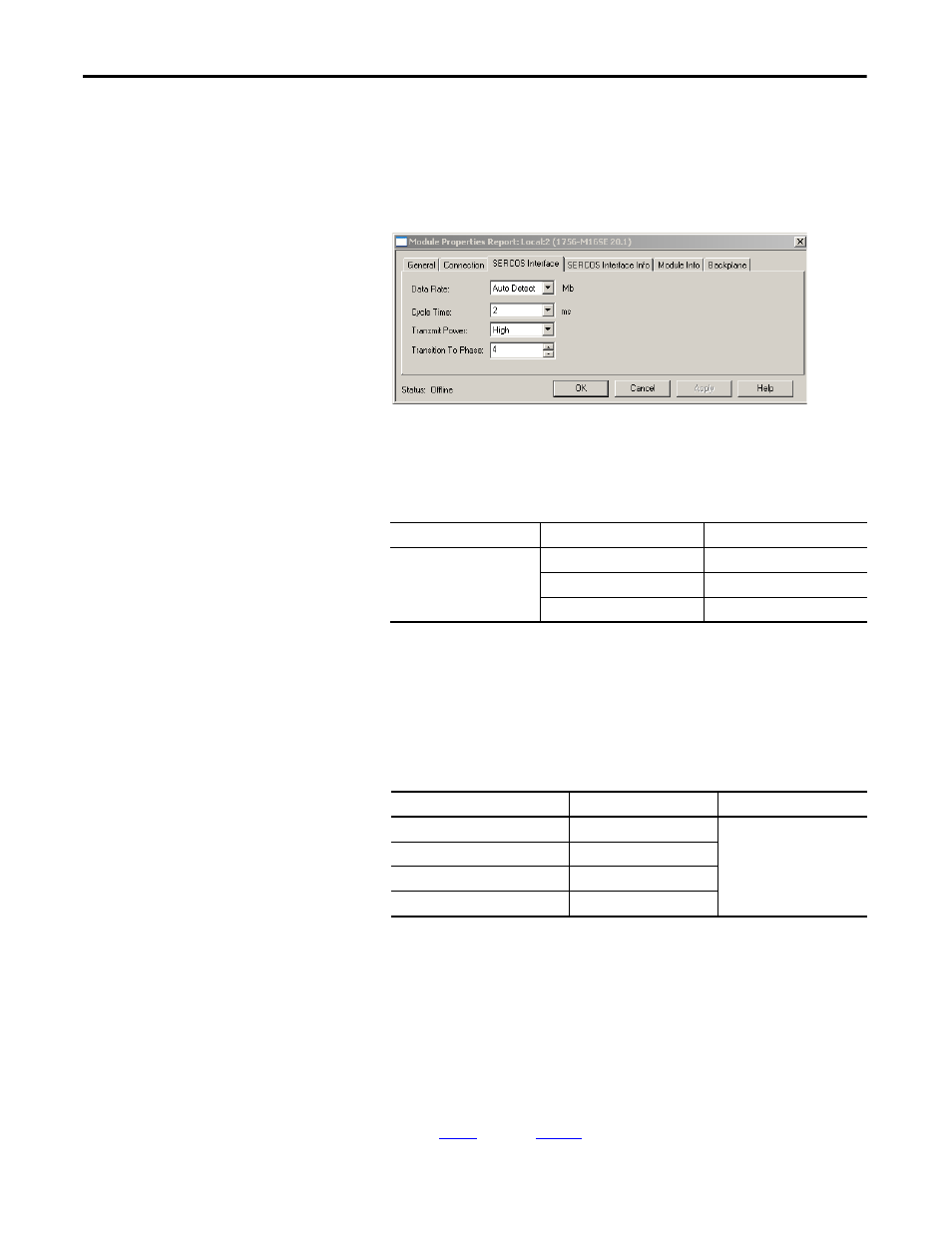
7. Click the SERCOS Interface tab.
8. From the Data Rate pull-down menu choose 8 Mb or choose the Auto
Detect setting.
9. From the Cycle Time pull-down menu, choose the Cycle Time according
to the table below.
10. From the Transmit Power pull-down menu, choose High.
The default setting is High; however, this setting is dependent on the cable
length (distance to next receiver) and cable type (glass or plastic).
11. Enter the Transition to Phase setting.
The Transition to Phase default setting is 4 (phase 4). The Transition to
Phase setting stops the ring in the phase specified.
through
for each Logix module.
TIP
The IDM system data rate is fixed at 8 Mbps.
Data Rate
Number of Axes
Cycle Time
8 Mbps
(1)
(1) The Kinetix 6000M system supports only 8 Mbps.
Up to 4
0.5 ms
Up to 8
1 ms
Up to 16
2 ms
TIP
The factory default data rate setting for all Kinetix 6000 modules is
4 Mbps.
TIP
The number of axes/module is limited to the number of axes as
shown in the table below.
Logix Sercos Module
Number of Axes
Data Rate
1756-M03SE or 1756-L60M03SE
Up to 3
8 Mbps
1756-M08SE
Up to 8
1756-M16SE or 1784-PM16SE
Up to 16
1768-M04SE
Up to 4