Idm unit connectors and indicators – Rockwell Automation MDF-SB1304F Kinetix 6000M Integrated Drive-Motor System User Manual
Page 43
Rockwell Automation Publication 2094-UM003A-EN-P - May 2012
43
Kinetix 6000M System Connector Data
Chapter 4
IDM Unit Connectors and
Indicators
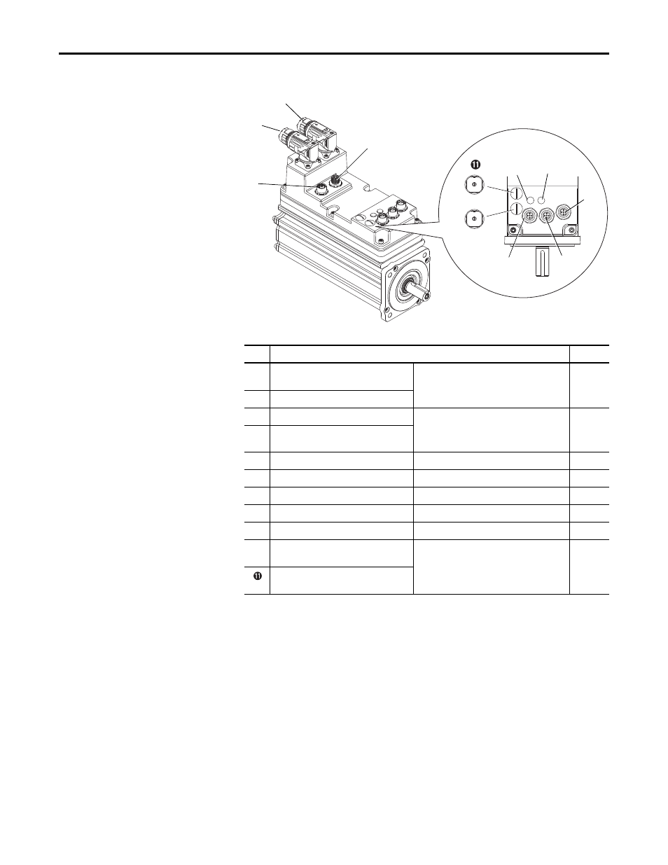
Figure 12 - Integrated Drive-motor Unit Features, Connectors, and Indicators
Item
Description
See page
➊
Hybrid cable input connector (from IPIM
module or previous IDM unit)
Input and output connecting points for the
Hybrid Power and Communication cables.
➋
Hybrid cable output connector (to IDM unit)
➌
IDM network output connector (to IDM unit)
Input and output connecting points for the IDM
network cables.
➍
IDM network input connector (from IPIM
module or previous IDM unit)
➎
Drive status indicator
Provides communication status for the IDM unit.
➏
Network status indicator
Provides general status for the IDM unit.
➐
HOME Digital Input (connector 3)
Digital input for home.
➑
REG1/OT+ Digital Input (connector 2)
Registration1/positive overtravel digital input.
➒
REG2/OT- Digital Input (connector 1)
Registration2/negative overtravel digital input.
➓
Node address switch S10 – 10’s digit (most
significant)
Sets the IDM network node address.
Node address switch S1 – 1’s digit (least
significant)
8 9
0
12
34
5
6 7
8 9
0
12
34
5
6 7
D
S1
S10
N
1
2
3
➋
➊
➏
➍
➎
➒
➑
➐
➌
➓